ProSoft Technology MVI56E-MCM/MCMXT User Manual
Page 61
MVI56E-MCM ♦ ControlLogix Platform
Configuration as a Modbus Slave
Modbus Communication Module
User Manual
ProSoft Technology, Inc.
Page 61 of 199
June 18, 2014
3.2.2 Customizing the Memory Map
In some cases, the above memory map will not work for the application.
Sometimes a Master must read bits starting at address 0001, and also read a
register starting at 40001. With the memory map in this Modbus Memory Map
(page 59), this is not possible, as W
RITE
D
ATA
[0]
is seen as both 0001 to 0016,
and 40001. To accommodate this, you can customize the starting location within
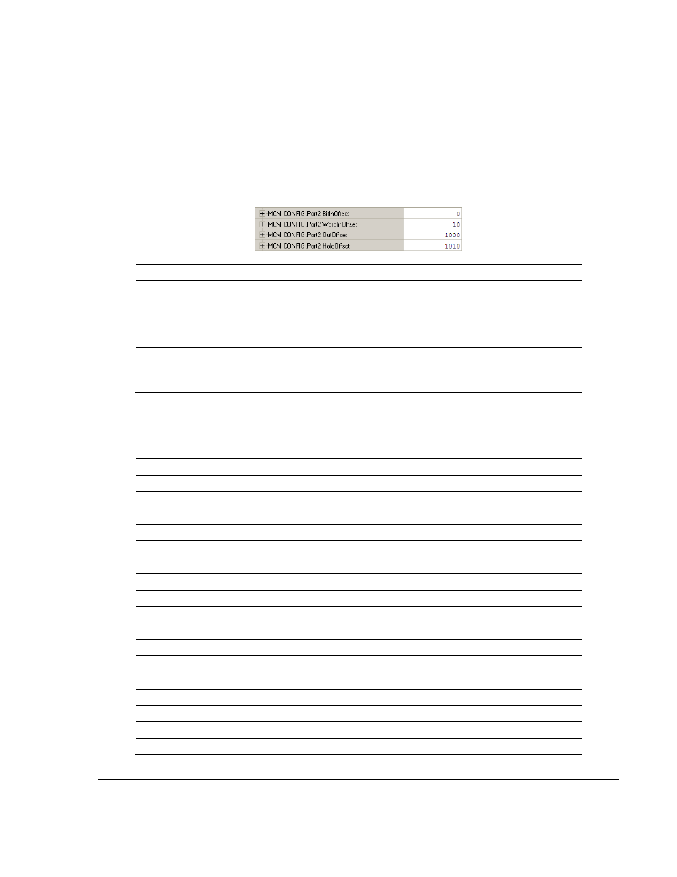
the module for each device using the parameters shown below.
Parameter
Value
Description
BitInOffset
0
Defines the starting address within the module for 1xxxx
Modbus addressing. A value of 0 sets 10001 to 10016 as
address 0 in the MVI56E-MCM module.
WordInOffset
10
Defines the starting address within the module memory for
3xxxx registers.
OutOffset
1000
Defines the starting address within the module for 0xxx coils.
HoldOffset
1010
Defines the starting address within the module for 4xxxx
addressing.
Based on the configuration described above for the ModDef section of the
module and the values specified for the offset parameters, below is the Modbus
addressing map for the module.
MVI Address 0xxx
1xxxx
3xxxx
4xxxx
Tag Address
0
10001 to 10016
WriteData[0]
1
10017 to 10032
WriteData[1]
9
10145 to 10160
WriteData[9]
10
10161 to 10176 30001
WriteData[10]
11
10177 to 10192 30002
WriteData[11]
100
11601 to 11616 30091
WriteData[100]
200
13201 to 13216 30191
WriteData[200]
500
18001 to 18016 30491
WriteData[500]
598
19569 to 19584 30489
WriteData[598]
599
19585 to 19600 30490
WriteData[599]
600 to 999
N/A
N/A
N/A
N/A
Reserved
1000
0001 to 0016
ReadData[0]
1001
0017 to 0032
ReadData[1]
1009
0145 to 0160
ReadData[9]
1010
0161 to 0176
40001
ReadData[10]
1011
0177 to 0192
40002
ReadData[11]
1050
0801 to 0816
40041
ReadData[50]