ProSoft Technology MVI56E-MCM/MCMXT User Manual
Page 120
Reference
MVI56E-MCM ♦ ControlLogix Platform
User Manual
Modbus Communication Module
Page 120 of 199
ProSoft Technology, Inc.
June 18, 2014
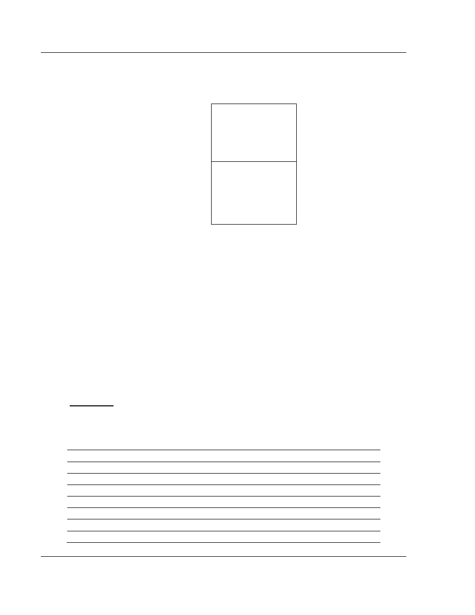
The following illustration shows the layout of the
module’s internal database
structure:
10,000 registers for user data
0
Register Data
9999
6000 words of configuration and
status data
10000
Status and Config
15999
Data contained in this database is paged through the input and output images by
coordination of the ControlLogix ladder logic and the MVI56E-MCM module's
program. Up to 248 words of data can be transferred from the module to the
processor at a time. Up to 247 words of data can be transferred from the
processor to the module. Each image has a defined structure depending on the
data content and the function of the data transfer as defined below.
6.2.3 Normal Data Transfer
Nor
mal data transfer includes the paging of the user data found in the module’s
internal database in registers 0 to 9999 and the status data. These data are
transferred through read (input image) and write (output image) blocks. Refer to
Using the Sample Program in an Existing Application (page 186) for a description
of the data objects used with the blocks and the ladder logic required. The
structure and function of each block is discussed below.
Read Block
These blocks of data transfer information from the module to the ControlLogix
processor. The following table describes the structure of the input image.
Read Block from Module to Processor
Word Offset
Description
Length
0
Reserved
1
1
Write Block ID: -1 to 50
1
2 to 201
Read Data
200
202
Program Scan Counter
1
203 to 204
Product Code
2
205 to 206
Product Version
2
207 to 208
Operating System
2