1794-ie4xoe2 memory map – ProSoft Technology 3170-PDP User Manual
Page 33
How Communication Takes Place and I/O Image Table Mapping
3170-PDP ♦ FLEX Platform
FLEX I/O™ PROFIBUS Adapter
ProSoft Technology, Inc.
Page 33 of 152
August 23, 2007
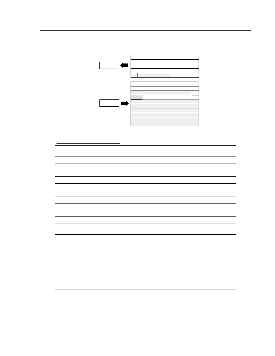
3.2.9 1794-IE4XOE2 – Analog Combo Module Image Table Mapping
Module Image
I/O Image
Input Data Channel 0
Input Data Channel 1
Input Data Channel 2
Input Data Channel 3
Output Data Channel 0
Output Data Channel 1
Underrange & Diag.
Not used
Not used
Not used
Not used
Not used
Not used
Not used
Full Range and Configure Select
Not used
Input Size
Output
0 to 4 Words
0 to 5 Words
Read
Write
OE
PU
1794-IE4XOE2 Memory Map
Decimal
Bit
15 14 13 12 11 10 09 08 07 06 05 04 03 02 01 00 Size
Oct.
Bit
17 16 15 14 13 12 11 10 07 06 05 04 03 02 01 00 Read
Words
S Analog Value Input Channel 0
Read Word 1
S Analog Value Input Channel 1
Read Word 2
S Analog Value Input Channel 2
Read Word 3
S Analog Value Input Channel 3
Read Word 4
PU Not used – set to 0
W1 W0 U3 U2 U1 U0 Read Word 5
S Analog Data – Output Channel 0
Write Word 1
S Analog Data – Output Channel 1
Write Word 2
Not used – set to 0
OE1 OE0 Write Word 3
Not
used C5 C4 C3 C2 C1 C0 0 0 F5 F4 F3 F2 F1 F0 Write
Word
4
Not used – set to 0
Write Word 5
thru 10
Where: PU = Power up bit – included in series B modules only.
W = Diagnostic bits for current output wire broken or load resistance high. (Not used on voltage
outputs.)
U = Underrange bits for 4 to 20mA inputs
OE = Output enable bits (bit 00 corresponds to output 0, bit 01 corresponds to output 1).
ATTENTION: These bits must be set to 1.
S = Sign bit (in 2's complement)
C = Configure select bit
F = Full range bit