Profibus adapter components, Diagnostic indicators, Network connector – ProSoft Technology 3170-PDP User Manual
Page 17: Profibus, Adapter components
Overview of FLEX I/O and Your PROFIBUS Adapter Module
3170-PDP ♦ FLEX Platform
FLEX I/O™ PROFIBUS Adapter
ProSoft Technology, Inc.
Page 17 of 152
August 23, 2007
2.5
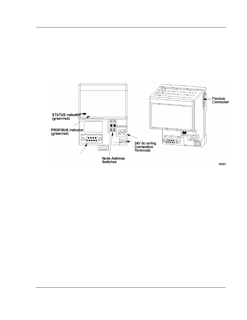
PROFIBUS Adapter Components
The adapter module consists of the following components:
two diagnostic indicators
PROFIBUS DP network connector
24V dc power wiring connection terminals
two node address switches
2.5.1 Diagnostic
Indicators
Diagnostic indicators are located on the front panel of the adapter module. They
show both normal operation and error conditions in your FLEX I/O system. The
indicators are:
Device status (STATUS)
Communication link status (PROFIBUS)
Upon power-up, the adapter goes to an initialization state and performs a self-
test (memory check, data memory clear. The indicators also go through a self-
test sequence. If a failure occurs, the adapter transitions to a faulted state and
waits for reset (cycle power). Otherwise, the adapter begins monitoring the
network (run state) for messages.
Chapter 5 describes the diagnostic indicators and how to use them for
troubleshooting.
2.5.2 Network
Connector
Use the 9-pin D-shell connector to connect your adapter to the PROFIBUS
network.