ProSoft Technology MVI56E-MNET/MNETXT User Manual
Page 30
Start Here
MVI56E-MNET / MNETXT ♦ ControlLogix Platform
User Manual
Modbus TCP/IP Interface Module
Page 30 of 181
ProSoft Technology, Inc.
April 23, 2014
Adjusting the Input and Output Array Sizes
Note: It is unnecessary to manually edit the ReadData and WriteData user-defined data types in
the ladder logic, as these are automatically updated to match the changed array sizes from ProSoft
Configuration Builder.
The module internal database is divided into two user-configurable areas:
Read Data
Write Data
The Read Data area is moved from the module to the processor, while the Write
Data area is moved from the processor to the module.
The MVI56E-MNET Add-On Instruction rung is configured for 600 registers of
Read Data and 600 registers of Write Data,
which is sufficient for most
applications. However, you can configure the sizes of these data areas to meet
the needs of your application.
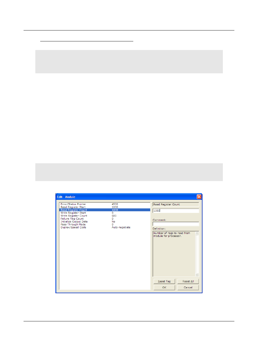
1 In ProSoft Configuration Builder, expand the Module icon in the tree view and
double-click M
ODULE
to open an Edit window. Change the R
EAD
R
EGISTER
C
OUNT
to contain the number of words for your Read Data area.
Important: Because the module pages data in blocks of 200 registers at a time, you should
configure your user data areas in multiples of 200 registers.
2 To modify the WriteData
array, follow the above steps, substituting WriteData
for ReadData.