To create an exhaust fan flow meter – Retrotec DM-2 User Manual
Page 43
Page 43 of 72
©Retrotec Inc. 2012
10. To view estimated flow at a different pressure, use the
[@ Pressure]
function.
11. Either press
[Set Speed]
to set the fan speed to a particular percentage, OR press
[Set
Pressure]
to control the fan to a particular building pressure.
12. Press
[Jog/Hold]
once and use the arrows to increase or decrease the speed/pressure, or
push it twice to “Hold” the results on the display to make them easier to copy down.
8.3 Measure Air Handler flow using Hole Flow on the gauge
The Retrotec gauge can be used to measure the amount of air flowing through a hole. This feature
enables the gauge to be used as an Exhaust Fan Flow Meter, by simply cutting a couple of holes in a
cardboard box. The open end of the flow box should have rough dimensions which are at least two
times the register dimensions, and the depth of the box should be at least the average of the other two
dimensions.
Because flow through a known size hole depends on pressure across the hole, and air flow into an
enclosed space will cause pressure, we can use a box with a hole in it to measure the system air flow.
This method partially blocks the flow from the air handler so readings are not exact, especially if
pressures in the box are above 8 Pa.
To create an Exhaust Fan Flow Meter
1. Cut a hole in one side of a medium-sized cardboard box where it
is only one layer thick, and leaving about one inch of cardboard
around the edge for stiffness.
2. Cut a 2" x 2" square hole in the center of the other side of the
box, again where the cardboard is only one layer thick. This is
the flow measuring hole. For accuracy, the small hole should be
at least 1.5 inches from the edge of the box and its area should
be less than half the area of the end of the box.
3. Tape any cracks in the other sides of the box to prevent air from
leaking.
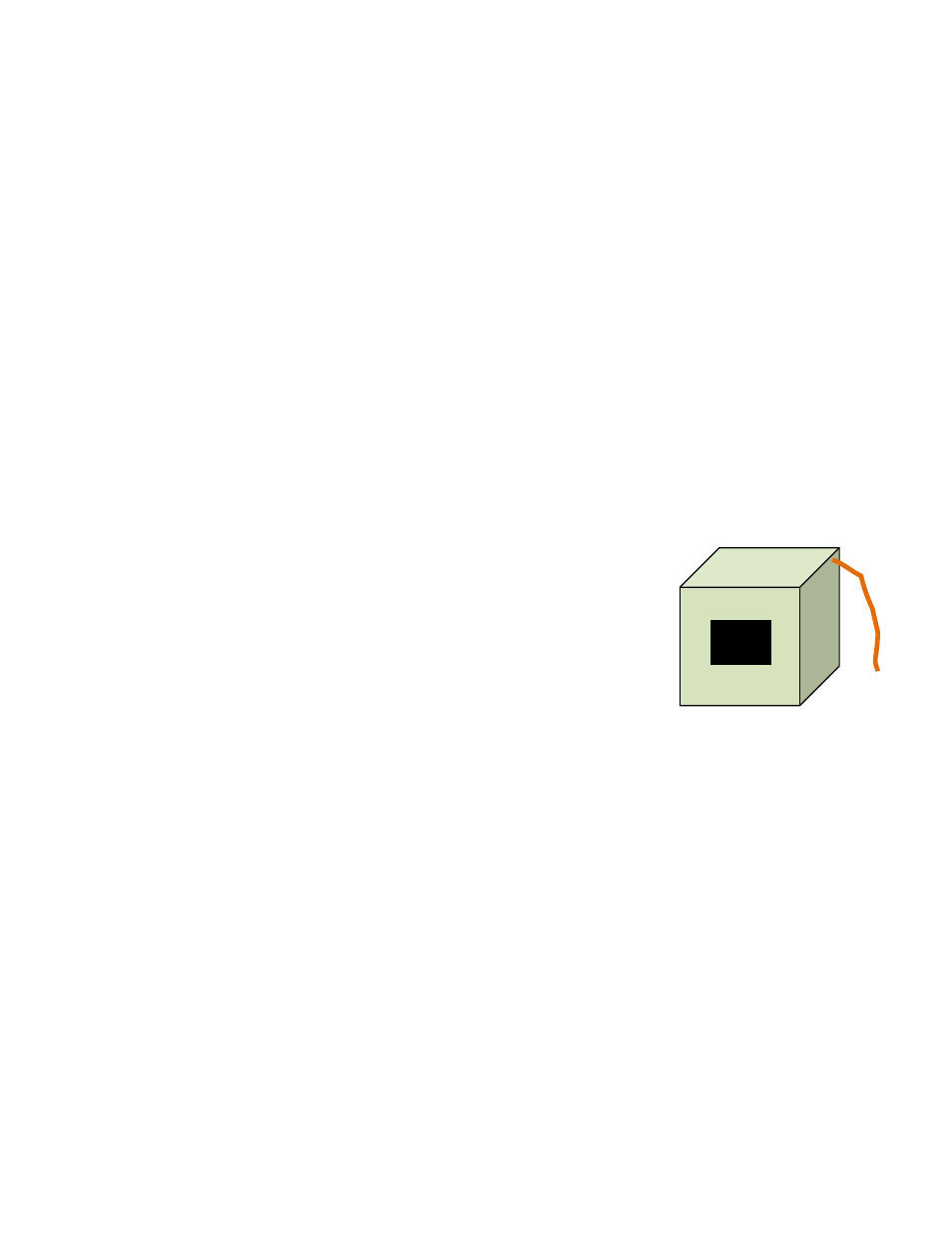
4. Punch a 0.25 inch diameter hole near a corner of the open end of the box for the pressure
tube. Insert a tube in the hole.
5. Connect the tube to the “Ref B” (yellow) and "Input A" (blue) ports of the gauge using a T
connector.
6. Fit the box over the exhaust fan grille while it is running, and seal in place around the box
edges.
7. Observe the pressure in the box on “PrA”. The same pressure will show on “PrB” if “Mode”
is set to Pressure.
8. Increase the size of the flow measuring hole in the box until the pressure is between 2 and 8
Pa.
9. If you have a Retrotec gauge, it can calculate the exhaust fan flow for you.
10. Set the “Mode” to “Hole Flow”.
11. Enter the area of the hole into the gauge using the [Area] key.
12. Read the Exhaust Flow in CFM directly from the gauge on Channel B, “Hole Flow”.
Figure 12: Exhaust fan flow
meter