Mode, Range config, 5 mode – Retrotec DM-2 User Manual
Page 13: 6 range config
Page 13 of 72
©Retrotec Inc. 2012
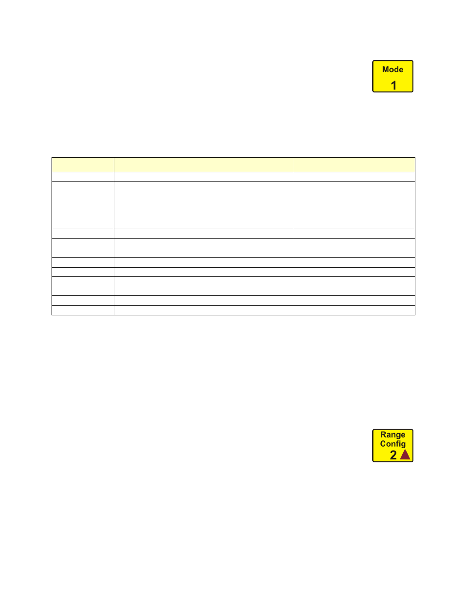
2.1.5 Mode
“Mode” refers to the measurements and results the DM-2 mark II can display. Each
Mode can also display in a variety of units. The top result line labeled “Pressure”
always displays Channel A pressure in the units chosen for “Pressure”. The second
result line labeled “Mode” displays the selected result in the chosen units. For information on setting
units for each Mode, see Section 3.3 Mode Setup. Table 2 lists all the Modes, the possible units that
can be set on the DM-2, and what the results mean (note that some results and units are not available
on all gauge models).
Table 2: Possible results and selectable units for the gauge
Mode
Measures
Units
Pressure
Fan Pressure through the fan
Pa, inches WC, lb/sq ft
Flow
Air flow through the fan
CFM, l/s, m
3
/s, m
3
/h
EfLA
Effective Leakage Area – calculated size of the total
hole in the Envelope. Usually taken at 4Pa in the US
cm
2
, sq in, sq ft
EqLA
Equivalent Leakage Area – calculated size of the total
hole in the Envelope. Usually taken at 10Pa in Canada
cm
2
, sq in, sq ft
Air Change
Number of air changes per hour
/h
Flow/Area
Air flow divided by the area of the enclosure
CFM/ sq ft, L/s
.
m
2
, CFM/100 sq ft,
m
3
/h
.
m
2
EfLA/Area
Effective Leakage Area divided by enclosure area
sq in/100 sq ft, cm
2
/m
2
EqLA/Area
Equivalent Leakage Area divided by enclosure area
sq in/100 sq ft, cm
2
/m
2
Hole Flow
The flow across a hole – to be used to measure flow
through a known hole size (like exhaust fan or register)
CFM, L/s, m
3
/s, m
3
/h
Velocity
Air velocity (requires pitot tube)
m/s, km/h, ft/s, ft/min, mph
Velocity Flow
Flow from velocity and area of duct
CFM, L/s, m3/s, m3/h
Press [Mode] to scroll through the results that have been activated in the Setup menu. If all modes are
activated then pressing [Mode] will cycle through the results in the following order:
Pressure Flow EqLA EfLA Air Changes Flow/Area EqLA/Area EqLA/Area
Hole Flow
Velocity
Velocity Flow
Older gauges have the velocity and velocity flow function.
When numerical input is required, the [Mode] key functions to input the number one, [1].
2.1.6 Range Config
Range Rings and Plates are used to limit the air flow through a fan, so that the fan can
achieve a measurable Fan Pressure, even when moving only a small amount of air (for
more information, see Manual - Door Fan Operations). Every fan that the gauge is
compatible with has a set of associated Range Configurations. Select the Range Configuration that
matches the Range Ring or Plate installed on the fan attached to the gauge to ensure that the gauge
performs accurate calculations, and displays correct results. Press [Range Config] to cycle through the
Range Configurations that are available for the currently selected device. Available Range
Configurations that are not used can be removed from the menu. See Enable and Disable Range
Configurations in Section 3.2 for detailed instructions.
When numerical input is required, the [Range Config] key functions to input the number two, [2].