Control connections – Retrotec DM-2 User Manual
Page 41
Page 41 of 72
©Retrotec Inc. 2012
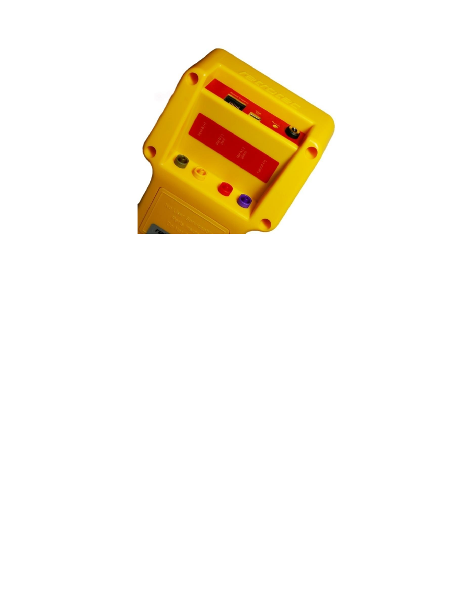
Figure 11: Pressure ports and control connections on the gauge.
8.1.2 Control connections
Speed Control – Connects the gauge to the fan using an Ethernet style cable.
CAUTION
: Never connect the speed control cable on the gauge (or the fan) to an internet
modem/router.
USB PC – The USB (Universal Serial Bus) port is used to connect the gauge to a computer equipped
with Retrotec’s FanTestic software to run tests automatically. The computer can assume complete
control of the gauge for data acquisition and control of advanced automated testing.
LCD Contrast dial (older models) – Adjust to increase or decrease the contrast of the display screen.
Higher contrast settings will increase the display screen legibility in low-light situations, but will
reduce battery life.
Power – Connects the gauge to an external power source using either the AC power adapter or
power available from the fan (if available).
To connect the gauge to a Retrotec fan or variable speed fan drive
1. Locate the end of the Umbilical cable (this is the bundle of pressure tubing and Control
Cable) with the shortest length of exposed pressure tubes and Control Cable. Plug the
yellow Control Cable into the Speed Control port on the gauge.
2. Plug colored tubes into the matching color-coded pressure ports on the top side of the
gauge. Ensure the tubes are snugly connected to the ports. Depending on the system,
Umbilical cable can contain red, yellow, green, and/or blue tubes.
Note: The power cord from the Umbilical to the gauge should not be attached unless the
batteries are below one quarter power, and require recharging.
3. From the other end of the Umbilical cable, plug the yellow Control Cable into the port
labeled “Control” on the fan.