B min, B max – MCZ Yari AIR User Manual
Page 21
B min
B max
K
K
J
J
B min
B max
19
3-INSTALLATION AND ASSEMBLY
CONNECTING THE HOT AIR DUCTING
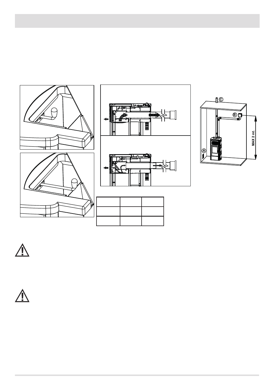
Once the stove is set in place, the hot air pipes can be installed.
For the first phase, it is necessary to select the air volume you wish have come out of the front part and rear of the stove.
This simple operation is carried out by using the mechanical lever located under the cover of the tank (Figure 3). The more it is open, the
more air will go through the front part and the less will go through the rear, and vice versa.
Figure 4 provides a clear description by providing a diagram of the distribution of hot air to the two outputs (front and rear) at the
maximum ventilation power and taking into account one duct.
Do not adjust air distribution using the lever when the stove is running or when the guards are removed: DANGER OR
BURNS. The metal parts near the lever can reach a temperature of 80°C.
Once the deflector is adjusted, connect the rear hot air outlet flange to the duct and outlet. The rear hot air outlet has a diameter of 80
mm. However, the pipe inserted in the wall must be adequately insulated in order not to disperse heat and soundproof the released air
With double ducting (two hot air outlets) it is advisable to use similar lengths for the two ducts to distribute the air
evenly, otherwise it will favour the shorter or straighter duct.
Figure 5 provides a simple example of ducting from the front view of the stove.
Technical Dept. - All rights reserved - Reproduction is prohibited
FIGURE 3 - Fan distribution adjustment
(front/rear)
FIGURE 4 - Front/rear hot air distribution
B
J
K
MIN
10%
90%
MAX
80%
20%
FIGURE 5 - Front view of air outlet system
Key figure 5
A = Cold air intake
B = hot air ducting and outlet
C = smoke outlet pipe