2 module disassembly – Pressure Systems 98RK-1 User Manual
Page 115
Pressure Systems, Inc. 98RK-1 & 9816 User’s Manual©
Page 113
www.PressureSystems.com
5.1.2
Module Disassembly
The following procedure should be used to remove modules from the 98RK-1 Scanner Interface
Rack prior to any scanner maintenance.
(1) Remove the module from the 98RK-1 Scanner Interface Rack by unscrewing the locking rod
(turn counterclockwise with a 5/64" Allen-head screwdriver) and slide the entire module chassis
out of the rack.
(2) Place the scanner on a flat surface. Remove the six (6) #0 Phillips-head screws that hold each
of the side covers on the scanner. Remove one or both side covers (if your maintenance
requires removal of both sides). Place the scanner with its front toward you. Notice that the
locking rod holes are drilled slightly off-center of the panel and that the rod extends to the side
of the tubing cluster. This facilitates removal of the transducer/cal-valve housing when
maintenance needs to be performed. Note,
DO NOT
completely remove the locking rod unless
there is an overriding need to do so. The small “c” spring clamp requires a special tool for
removal and the clamp itself is easily lost.
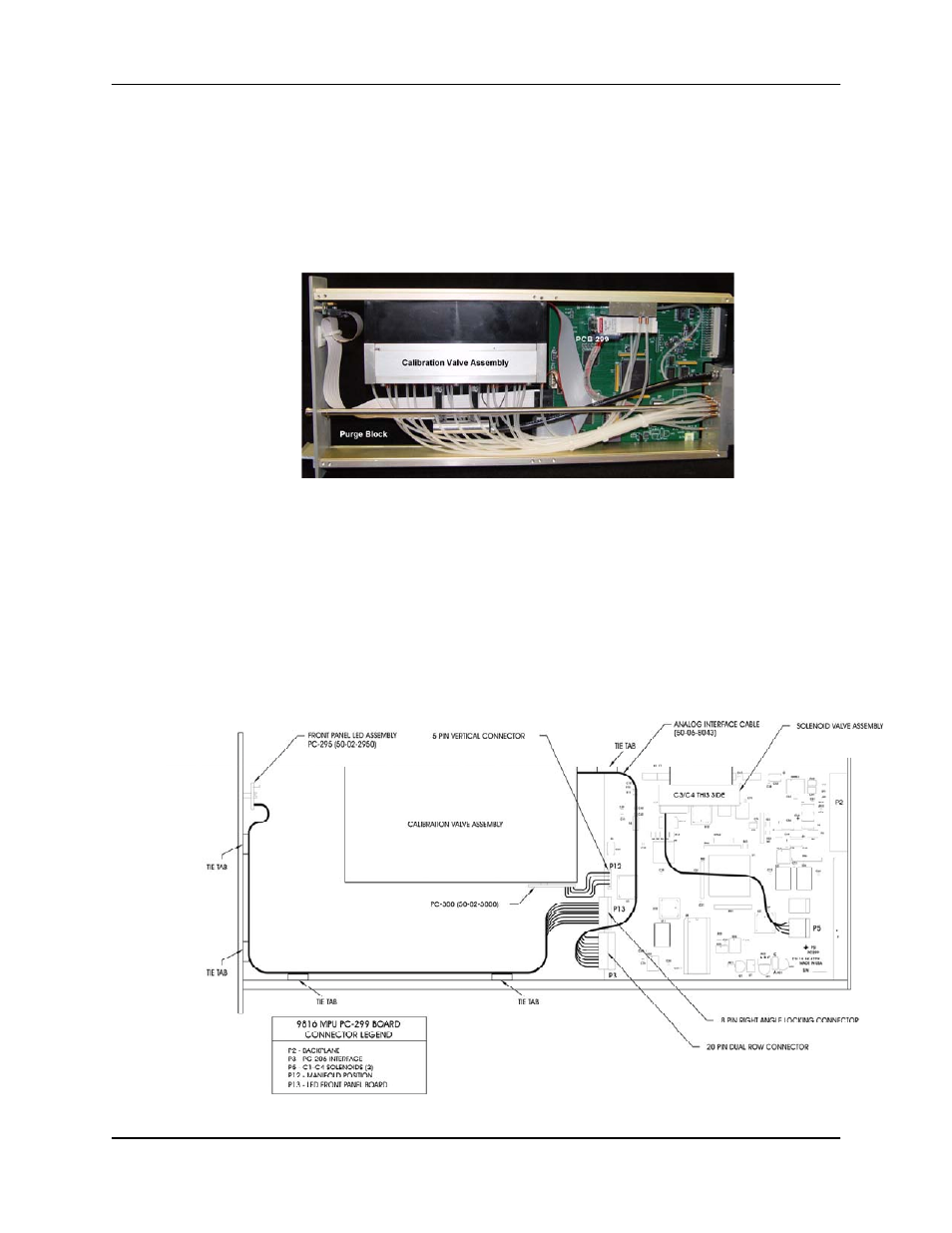
(3) If your maintenance requires doing so, unplug the manifold position detector four-pin connector
from the PC-299 board at P-12 (see Figure 5.3 below).
Figure 5.3
PC299 Board