Span calibration valve control – Pressure Systems 98RK-1 User Manual
Page 106
Pressure Systems, Inc. 98RK-1 & 9816 User’s Manual©
Page 104
www.PressureSystems.com
stored back into the transducer’s nonvolatile memory afterwards. In other cases, the user’s
application may not require periodic span adjustment as the other factory-determined
pressure/temperature coefficients (stored permanently inside each transducer) are extremely
stable. Only an occasional Re-zero adjustment may be all that is necessary.
When instructed to execute a Calculate and Set Gains ('Z') command, the module will perform
the Span adjustment calibration, and then update the gain coefficients in its volatile memory. It
will subsequently use the newly calculated gain terms for subsequent engineering-unit
calculations.
Note
When using the Calculate and Set Gain ('Z') command, only the
local variables in the module’s volatile main memory (RAM) are
changed. Refer to Section 4.5 if it is desired to also store these new
gain coefficients in transducer nonvolatile memory.
4.3.1.
Span
Calibration
Valve
Control
Before executing a Span adjustment (Calculate and Set Gains ('Z') command), Model 9816
modules should have their calibration manifold valve placed in the proper position. For single
pressure range units, the CAL position should be used since the span calibration pressure can
be applied between the CAL 1-8 and CAL REF ports. Since the module will not attempt to shift
this valve automatically, as it does for Re-zero adjustment, it should be placed in the desired
position manually with the Set Operating Options ('w') command (option indexes = 0C and
12).
When span calibrating Model 9816 modules with multiple ranges installed, the CAL port may be
used to apply pressure to all transducers only if the specified proof pressure is not
exceeded on any channel. If the application of a specific span pressure exceeds the proof
pressure rating of any other transducer contained within the same scanner, the calibration
pressures must be applied to the RUN side pneumatic input ports. Since the calibration
command ('Z') has a channel selection bit map parameter allowing it to calibrate only the
desired pressure channels, the RUN port is a viable option for supplying the calibration
pressures.
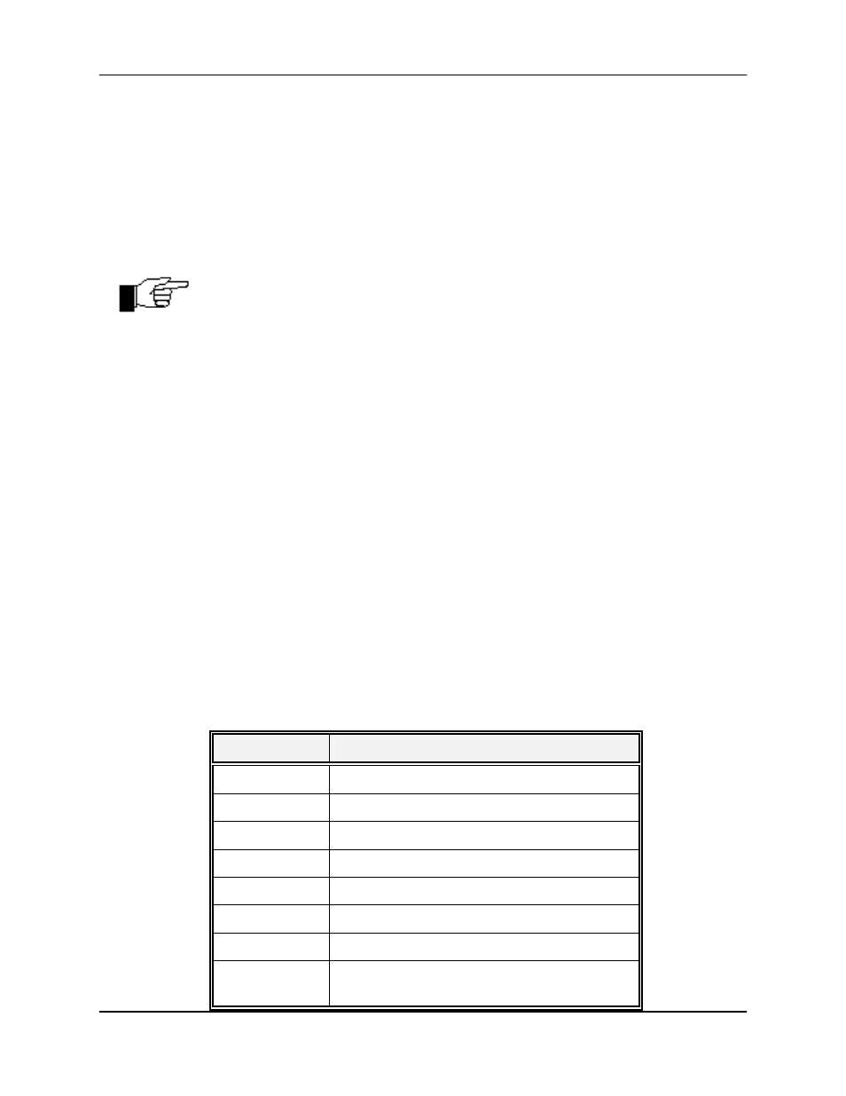
Pneumatic Connector Assignment on Rear Input Panel of the 98RK-1
Connection
Pressure Scanner Range Input
Cal 1
User defined
Cal 2
10" W.C.; 20" W.C.; ±1 psid, ±1.5 psid
Cal 3
±2.5; ±5 psid
Cal 4
±10; ±15 psid, ±20 psid, ±25 psid
Cal 5
±30; ±45; ±50 psid
Cal 6
±75 psid, ±100 psid
Cal 7
+ 150; 200; 250; 300 psid
Cal 8
500 psid, 600 psid, 650 psid, 750 psid, 850
psid