1 interfaces, Serial interface rs 232, Interfaces, peripherals – Epson USN 52L User Manual
Page 129
8-2
Issue 05, 02/00
Krautkramer USN 52R/USN 52L
8.1
Interfaces
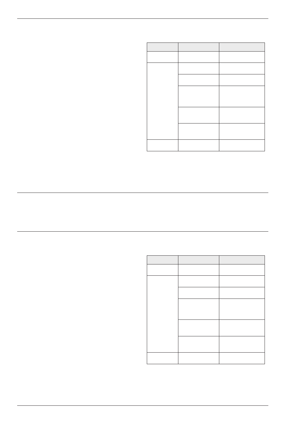
Serial interface RS 232
The 7 pin connector at the back of the instrument is the
bidirectional interface RS 232. It enables data transfer
to an external device, e.g. printer, PC or the DR1 Data
Recorder from Krautkrämer.
The instrument can also receive data transferred from a
PC. All keyboard controls and functions are accessible.
The measurement report and other data can be trans-
ferred using A. The COPY MODE in the lower level
sets the data communication initiated by A.
The table opposite gives an overlook into RS 232 out-
put possibilities of the instrument.
H Note:
Use the correct connection cable for each peripheral.
Refer to Chapter 2.
Interfaces, Peripherals
Interfaces
t
n
e
m
u
r
t
s
n
I
E
D
O
M
Y
P
O
C
t
u
p
t
u
O
t
n
e
m
u
r
t
s
n
i
o
N
R
E
G
G
O
L
A
T
A
D
s
e
r
o
t
s
y
ll
a
n
r
e
t
n
I
t
n
e
m
e
r
u
s
a
e
m
d
e
y
a
l
p
s
i
d
r
e
t
n
i
r
p
l
a
i
r
e
S
Y
P
O
C
D
R
A
H
y
a
l
p
s
i
d
R
2
5
N
S
U
t
n
e
t
n
o
c
T
R
O
P
E
R
T
R
O
P
E
R
r
e
g
g
o
L
a
t
a
D
s
c
i
t
s
i
t
a
t
s
d
n
a
s
b
o
J
h
t
i
w
P
M
U
D
P
+
P
S
I
D
y
a
l
p
s
i
d
n
a
c
S
-
A
e
v
i
t
c
A
R
2
5
N
S
U
s
a
ll
e
w
s
a
e
v
i
t
c
a
d
n
a
s
n
o
i
t
c
n
u
f
s
g
n
i
t
t
e
s
P
M
U
D
R
E
T
E
M
A
R
A
P
e
t
o
m
e
r
,
t
s
il
n
o
i
t
c
n
u
F
l
a
u
t
c
a
d
n
a
s
e
d
o
c
s
g
n
i
t
t
e
s
P
M
U
D
O
M
E
M
h
t
i
w
s
d
r
o
c
e
r
a
t
a
D
d
n
a
r
e
b
m
u
n
,
e
m
a
n
s
n
o
i
t
a
m
r
o
f
n
i
l
a
n
o
i
t
i
d
d
a
e
c
i
v
e
d
-
2
3
2
S
R
)
r
e
t
n
i
r
p
,
C
P
(
S
S
E
N
K
C
I
H
T
l
a
t
i
g
i
d
d
e
y
a
l
p
s
i
d
e
h
T
e
u
l
a
v
t
n
e
m
e
r
u
s
a
e
m
8-2
Issue 05, 02/00
Krautkramer USN 52R/USN 52L
8.1
Interfaces
Serial interface RS 232
The 7 pin connector at the back of the instrument is the
bidirectional interface RS 232. It enables data transfer
to an external device, e.g. printer, PC or the DR1 Data
Recorder from Krautkrämer.
The instrument can also receive data transferred from a
PC. All keyboard controls and functions are accessible.
The measurement report and other data can be trans-
ferred using A. The COPY MODE in the lower level
sets the data communication initiated by A.
The table opposite gives an overlook into RS 232 out-
put possibilities of the instrument.
H Note:
Use the correct connection cable for each peripheral.
Refer to Chapter 2.
Interfaces, Peripherals
Interfaces
t
n
e
m
u
r
t
s
n
I
E
D
O
M
Y
P
O
C
t
u
p
t
u
O
t
n
e
m
u
r
t
s
n
i
o
N
R
E
G
G
O
L
A
T
A
D
s
e
r
o
t
s
y
ll
a
n
r
e
t
n
I
t
n
e
m
e
r
u
s
a
e
m
d
e
y
a
l
p
s
i
d
r
e
t
n
i
r
p
l
a
i
r
e
S
Y
P
O
C
D
R
A
H
y
a
l
p
s
i
d
R
2
5
N
S
U
t
n
e
t
n
o
c
T
R
O
P
E
R
T
R
O
P
E
R
r
e
g
g
o
L
a
t
a
D
s
c
i
t
s
i
t
a
t
s
d
n
a
s
b
o
J
h
t
i
w
P
M
U
D
P
+
P
S
I
D
y
a
l
p
s
i
d
n
a
c
S
-
A
e
v
i
t
c
A
R
2
5
N
S
U
s
a
ll
e
w
s
a
e
v
i
t
c
a
d
n
a
s
n
o
i
t
c
n
u
f
s
g
n
i
t
t
e
s
P
M
U
D
R
E
T
E
M
A
R
A
P
e
t
o
m
e
r
,
t
s
il
n
o
i
t
c
n
u
F
l
a
u
t
c
a
d
n
a
s
e
d
o
c
s
g
n
i
t
t
e
s
P
M
U
D
O
M
E
M
h
t
i
w
s
d
r
o
c
e
r
a
t
a
D
d
n
a
r
e
b
m
u
n
,
e
m
a
n
s
n
o
i
t
a
m
r
o
f
n
i
l
a
n
o
i
t
i
d
d
a
e
c
i
v
e
d
-
2
3
2
S
R
)
r
e
t
n
i
r
p
,
C
P
(
S
S
E
N
K
C
I
H
T
l
a
t
i
g
i
d
d
e
y
a
l
p
s
i
d
e
h
T
e
u
l
a
v
t
n
e
m
e
r
u
s
a
e
m