Epson USN 52L User Manual
Page 105
5-60
Issue 05, 02/00
Krautkramer USN 52R/USN 52L
ANGLE Angle of incidence
You must set the value of the applied probe in order to
enable automatic flaw location evaluation.
Operation:
– Set the required angle with M in ANGLE
(minimum 10°).
– In order to disable the flaw location calculation, press
N and O simultaneously or set the function to OFF.
H Note:
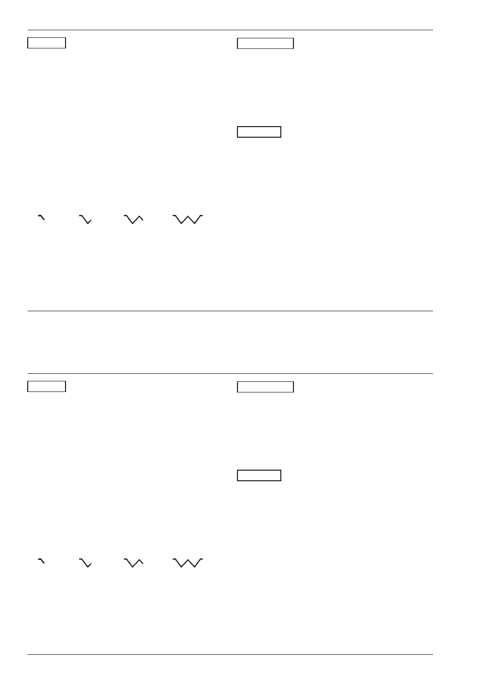
If you are working with an angle-beam probe and set
the ANGLE function then, depending on the number of
echo reflections, a symbol will be displayed in the sta-
tus line:
THICKNESS Material thickness
To determine the true depth, you must enter the thick-
ness of the material.
Operation:
– Set the thickness with M in the THICKNESS
function.
X-VALUE X-value of the probe
In this function you set the distance from the beam
index point to the front edge of the probe (refer to the
diagram on the previous page). This is determined me-
chanically with a ruler. The setting of the X-value is
necessary when the instrument is to determine the
reduced projection distance.
Operation:
– Set the X-value with M in the X-VALUE function.
Operation
Setting the flaw location calculation
5-60
Issue 05, 02/00
Krautkramer USN 52R/USN 52L
ANGLE Angle of incidence
You must set the value of the applied probe in order to
enable automatic flaw location evaluation.
Operation:
– Set the required angle with M in ANGLE
(minimum 10°).
– In order to disable the flaw location calculation, press
N and O simultaneously or set the function to OFF.
H Note:
If you are working with an angle-beam probe and set
the ANGLE function then, depending on the number of
echo reflections, a symbol will be displayed in the sta-
tus line:
THICKNESS Material thickness
To determine the true depth, you must enter the thick-
ness of the material.
Operation:
– Set the thickness with M in the THICKNESS
function.
X-VALUE X-value of the probe
In this function you set the distance from the beam
index point to the front edge of the probe (refer to the
diagram on the previous page). This is determined me-
chanically with a ruler. The setting of the X-value is
necessary when the instrument is to determine the
reduced projection distance.
Operation:
– Set the X-value with M in the X-VALUE function.
Operation
Setting the flaw location calculation