12 setting the flaw location calculation – Epson USN 52L User Manual
Page 104
Krautkramer USN 52R/USN 52L
Issue 05, 02/00
5-59
5.12 Setting the flaw location
calculation
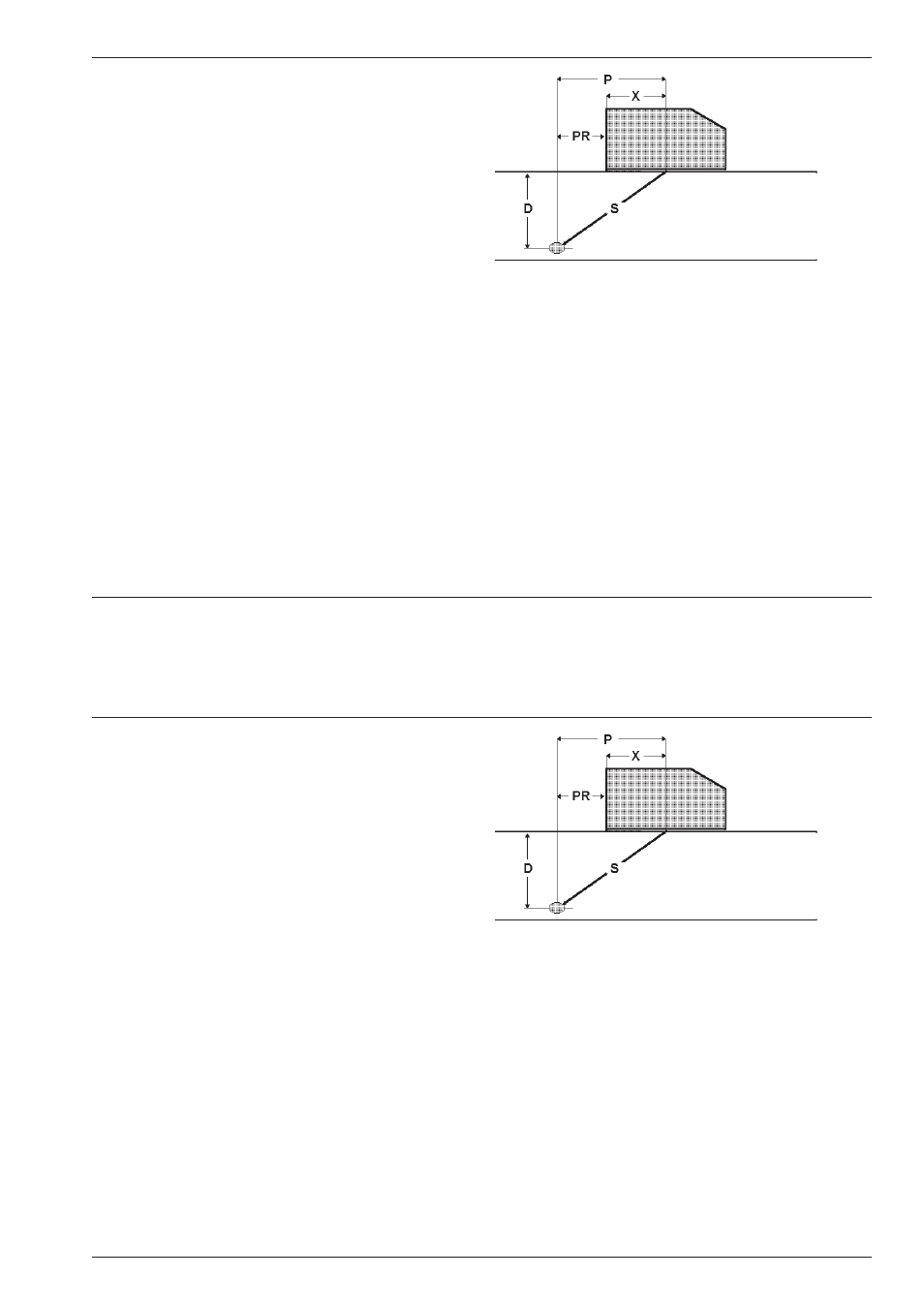
When using angle-beam probes, the flaw location can
be automatically calculated. The following values are
indicated on the display:
• Sound path
• Reduced projection distance: The distance from
the front edge of the probe to the location of the flaw,
projected on the surface
• Depth: Distance from flaw location to surface
The illustration on the next page shows the relationship
between these values.
H Note:
The gate must be enabled and the MEASURE function
set to “0 TO 1st“.
– With U go to center function table.
All the necessary functions are available in the right
group.
P
projection distance
PR
reduced projection distance
X
distance probe edge – beam index point
S
effective sound path
D
distance flaw location – surface
Setting the flaw location calculation
Operation
Krautkramer USN 52R/USN 52L
Issue 05, 02/00
5-59
5.12 Setting the flaw location
calculation
When using angle-beam probes, the flaw location can
be automatically calculated. The following values are
indicated on the display:
• Sound path
• Reduced projection distance: The distance from
the front edge of the probe to the location of the flaw,
projected on the surface
• Depth: Distance from flaw location to surface
The illustration on the next page shows the relationship
between these values.
H Note:
The gate must be enabled and the MEASURE function
set to “0 TO 1st“.
– With U go to center function table.
All the necessary functions are available in the right
group.
P
projection distance
PR
reduced projection distance
X
distance probe edge – beam index point
S
effective sound path
D
distance flaw location – surface
Setting the flaw location calculation
Operation