8 ac wiring confi guration (me2000 models), Installation – Magnum Energy ME Series User Manual
Page 39
Page 31
©
2012 Magnum Energy, Inc.
Installation
2.5.8
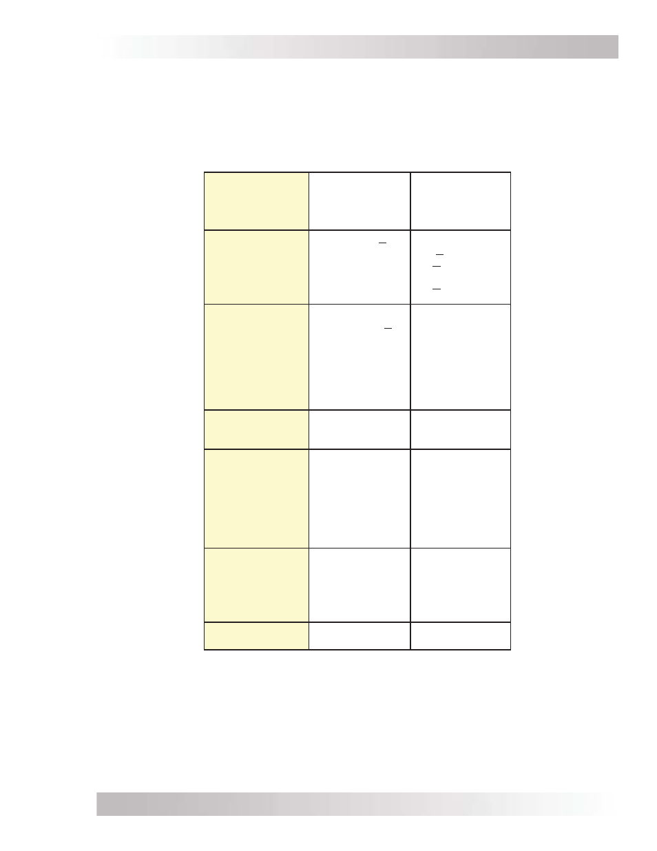
AC Wiring Confi guration (ME2000 models)
The following table provides the different wiring confi gurations for installing and connecting the
AC conductors into and out of ME2000 model inverters (see Figures 2-14 and 2-15 for installation
diagrams showing these confi gurations).
Table 2-4, AC Input/Output Wiring Confi gurations (ME2000 models)
Models
ME2000
ME2000-15B
ME2000-20B
AC Source
1
Required
120 VAC @ <30
amps
120 VAC @
<30 amps
@ <15 amps per
leg (-15B models);
or <20 amps per
leg (-20B models).
Reason to Use
Have an 120 VAC
source that is <30
amps.
Requires a
separate inverter
sub-panel.
Do not want to
install a separate
inverter sub-panel.
Inverter pass-thru
capability limited
by model used.
Wiring
Confi gurations
SI/SO (30A)
Single In/Single
Out (30A)
SI/DO
Single In/
Dual Out
Maximum Input
Breaker Required
-
Minimum Wire
Size
30A
(single pole)
-
#12 AWG
(In & Out)
-15B models:
30A (single pole);
-20B models:
30A (single pole)
-
#12 AWG (In)
#12 AWG x2 (Out)
Maximum
Inverter Pass-
thru capacity
3600W
(30A @ 120 VAC)
-15B models:
15A/leg
(30A max.);
-20B models:
20A/leg
(30A max.)
Wiring Diagram
Figure 2-14
Figure 2-15
Note
1
: AC source is from either utility power or an
onboard generator.