Installation – Magnum Energy ME Series User Manual
Page 32
©
2012 Magnum Energy, Inc
Page 24
Installation
2.5.6
AC Wiring Confi guration (ME2012, ME2512, and ME3112 models)
The following table provides the different wiring confi gurations for installing and connecting the AC
conductors into and out of the ME2012, ME2512, and ME3112 model inverters (see Figures 2-9
to 2-13 for installation diagrams showing these confi gurations). Refer to Table 2-4 (and Figures
2-14 & 2-15) for the ME2000 models.
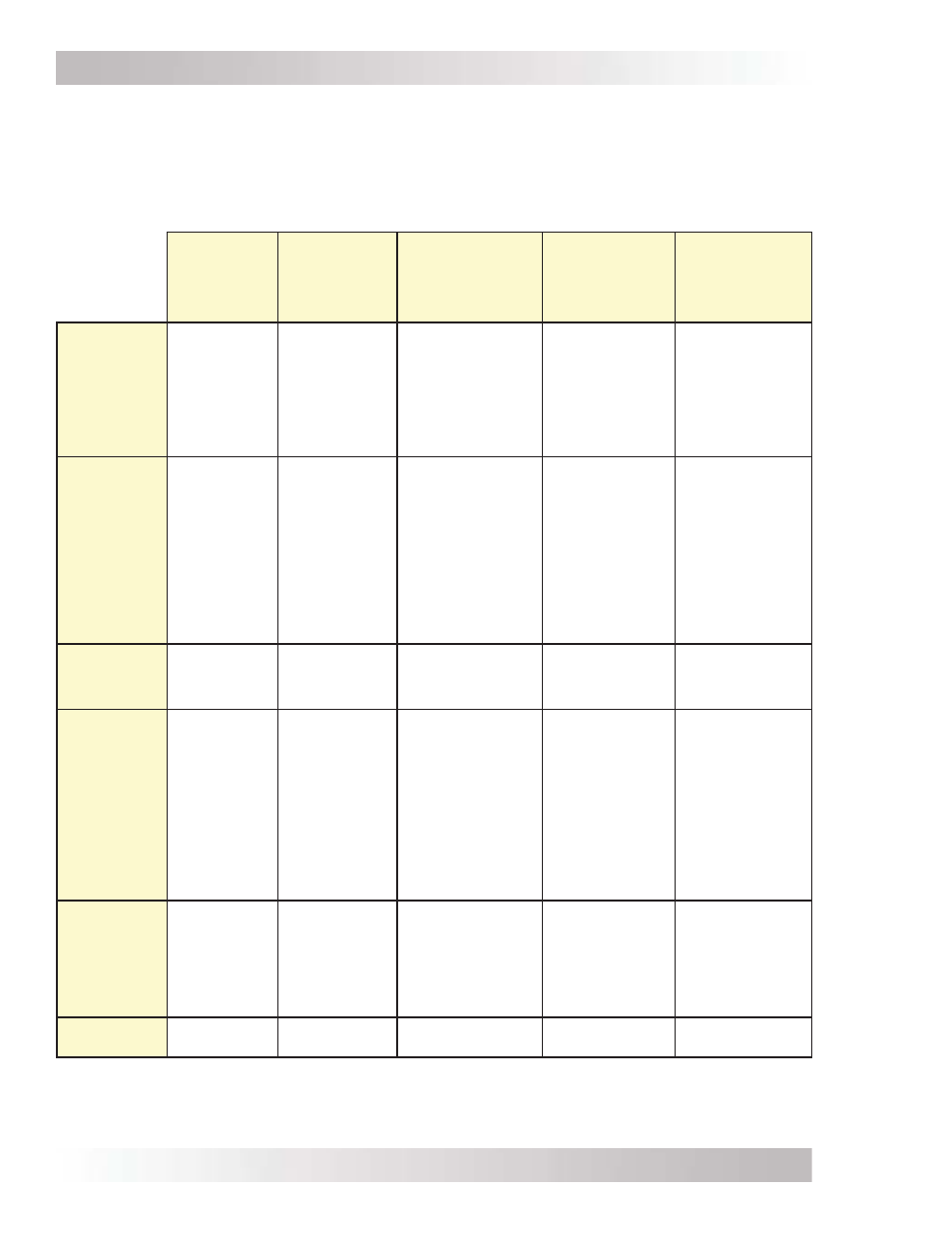
Table 2-3, AC Input/Output Wiring Confi gurations
SI/SO
(30A)
Single In/
Single Out
(30A)
SI/SO (60A)
Single In/
Single Out
(60A)
SI/DO
Single In/
Dual Out
DI/SO
Dual In/
Single Out
DI/DO
Dual In/
Dual Out
AC Source
1
Required
120 VAC @
≤30 amps
120 VAC @
>30 amps
(60 amps
maximum).
120 VAC @
≤30 amps
@ ≤15 amps per
leg (-15B models);
or ≤20 amps per
leg (-20B models).
120/240 VAC (or
2 separate legs
of 120 VAC)
@ ≤30 amps per
leg
120/240 VAC (or
2 separate legs
of 120 VAC)
@ ≤30 amps per
leg
Reason to
Use
Have an 120
VAC source
that is ≤30
amps.
Requires
a separate
inverter
sub-panel.
Have an 120
VAC source
that is >30
amps.
Requires
a separate
inverter
sub-panel.
Do not want to
install a separate
inverter sub-panel.
Inverter pass-thru
capability limited
on each leg by
model used.
Want dedicated
charging and
dedicated pass-
thru while the
AC source is on.
Requires a
separate inverter
sub-panel.
May need to
power 240 VAC
loads when
AC source is
on (requires
120/240 VAC
source).
Requires a
separate inverter
sub-panel.
Appropriate
Models
ME2012
ME2512
ME3112
ME2012
ME2512
ME3112
ME2012-15B
ME2012-20B
ME2012
ME2512
ME3112
ME2012
ME2512
ME3112
Maximum
Input
Breaker
Required
-
Minimum
Wire Size
(AWG)
30A
(single pole)
-
#10 AWG
(In & Out)
60A
(single pole)
-
#6 AWG
(In & Out);
Hot input and
output must
be split to two
#10 AWG
For full charging
and pass-thru
-15B=45A SP
-20B=60A SP
-
-15B In=#8
(split to #12 x2)
-20B In=#6
(split to #10 x2)
-15B Out=#12 x2
-20B Out=#10 x2
30A
(dual pole)
-
#10 AWG
(In & Out)
30A
(dual pole)
-
#10 AWG
(In & Out)
Maximum
Inverter
Pass-thru
capacity
3600W
(30A @
120 VAC)
7200W
(60A @
120 VAC)
-15B models:
15A/leg
(30A max.);
-20B models:
20A/leg
(40A max.)
3600W
(30A @
120 VAC)
7200W
(2 legs of 30A @
120/240 VAC or
2 legs of 30A @
120 VAC)
2
Wiring
Diagram
Figure 2-9
Figure 2-10
Figure 2-11
Figure 2-12
Figure 2-13
Note
1
: AC source is from either the utility/grid power (i.e., shorepower) or an AC generator.
Note
2
: If two legs of 30A @ 120 VAC are used, they must be from the same source (i.e., have a common
neutral).