Magnum Energy ME Series User Manual
Page 11
Page 3
©
2012 Magnum Energy, Inc.
Introduction
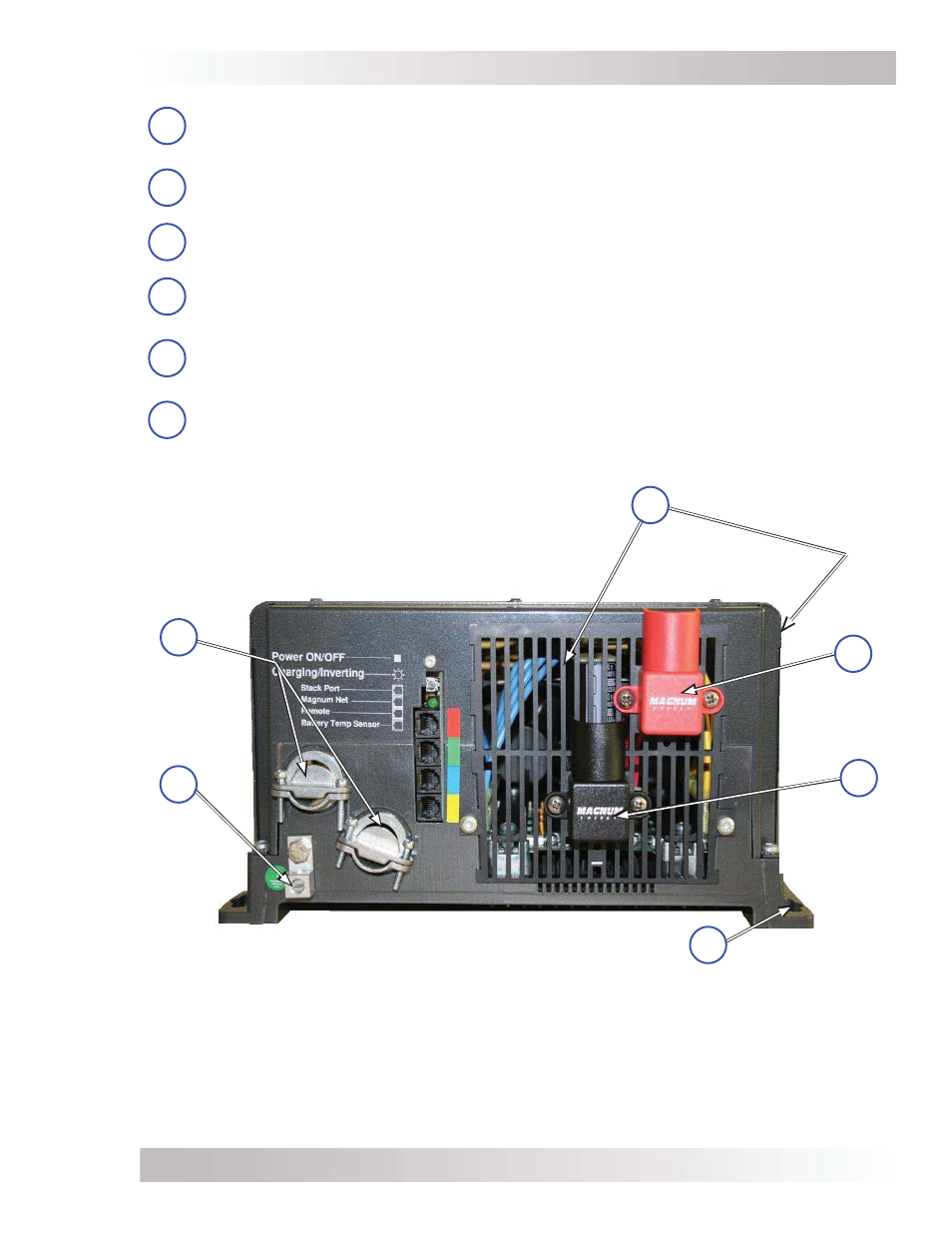
Figure 1-2, Electrical Connection Points
Intake Air Vents
(and on right side)
AC Input/
Output
Connections
DC
Equipment
Ground
Terminal
Positive (+)
DC terminal
(under cover)
Negative (-)
DC terminal
(under cover)
11
10
7
8
Mounting
Flange
7
DC Equipment Ground Terminal – this connection is used to tie the exposed chassis
of the inverter to the DC grounding system. This terminal accepts CU/AL conductors from
#14 to #2 AWG (2.1 to 33.6 mm
2
).
8
AC Input/Output Connections – two 3/4” knockouts provided with cable-clamp
strain
relief
s to allow and hold the AC input and output
fi eld
wiring.
9
Intake Air Vents – ventilation openings to pull in air to help keep the inverter cool for
peak performance.
10
Positive DC Terminal – provides 360 degree connection point for the positive (+) cable
from the battery bank; provided with a Kep or Flange nut on a 5/16-18 bolt to hold the
battery cable to the DC terminal.
11
Negative DC Terminal – provides 360 degree connection point for the negative (–) cable
from the battery bank; provided with a Kep or Flange nut on a 5/16-18 bolt to hold the
battery cable to the DC terminal.
12
Mounting Flange – used to secure the inverter to a shelf or wall.
9
12