2 connecting the external power supply, Connecting the external power supply, Notice – KACO Powador Argus 16S DCS User Manual
Page 16
Installing the String Monitoring Box
Page 16
Operating Instructions Powador Argus 16S DCS, 24S DCS_EN
Authorised electrician
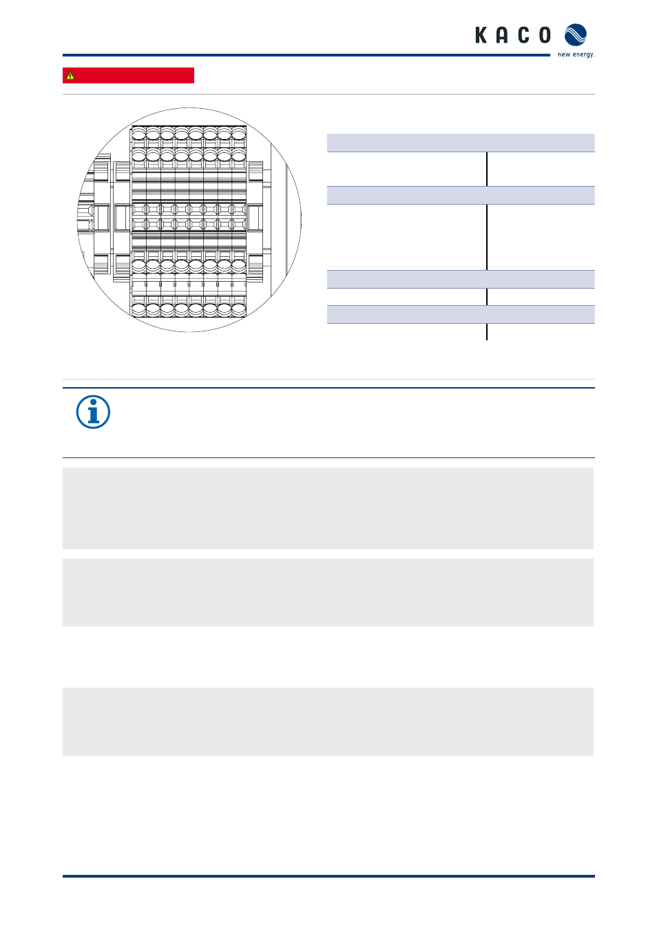
Communication leads for terminal assignment:
RS485 bus connection:
1 ... RS485-1 A
9 ... RS485-1 B
2 ... RS485-2 A
10 ... RS485-2 B
Analogue inputs (0 V to 10 V):
3 ... Sensor (1) +
4 ... Sensor (2) +
5 ... Sensor (3) +
6 ... Sensor (4) +
11 ... Sensor (1) -
12 ... Sensor (2) -
13 ... Sensor (3) -
14 ... Sensor (4) -
Power supply:
7 ... 24 V +
15 ... 24 V GND
I/O sensor connection:
8 ... I/O sensor A
16 ... I/O sensor B
Figure 8: Connection of the communication leads using spring-type terminals
NOTICE
The box is equipped with grey spring-type terminals for connecting the communication leads.
It is possible to connect these terminals with leads from 0.25 mm² to 2.5 mm². Operating tool:
Screwdriver, type 2, blade 3.5 mm x 0.5 mm.
Connection for communication leads
1. Unscrew the cable fittings until you can insert the stripped ends of the cables through the multi-cable sealing
inserts of the fittings.
2. Connect the stripped ends of the cable to the grey spring-type terminals.
3. Ensure polarity is correct when connecting the leads.
Checking the communication leads
1. Double-check that all connected leads are securely connected.
2. Tighten the cable seal of the cable fittings.
3. Close any unused openings of the cable fittings.
7.2
Connecting the external power supply
Connect the external power supply to the grey double-deck spring-type terminals (7 ... 24 V + and 15 ... 24 V GND).
Connecting the external power supply
1. Unscrew cable fitting (M25).
2. Connect ends of cables to the PCB terminals according to their marking.
3. Tighten the cable seal of the cable fitting.