1 connection for communication leads, Connection for communication leads, 1 connecting the rs485 bus – KACO Powador Argus 16S DCS User Manual
Page 15
Installing the String Monitoring Box
Operating Instructions Powador Argus 16S DCS, 24S DCS_EN
Page 15
Authorised electrician
7.1
Connection for communication leads
The string monitoring box is equipped with grey double-deck spring-type terminals for connecting the communi-
cation leads. The cable fittings for the connection of these leads are located underneath the housing on the right
side.
7.1.1
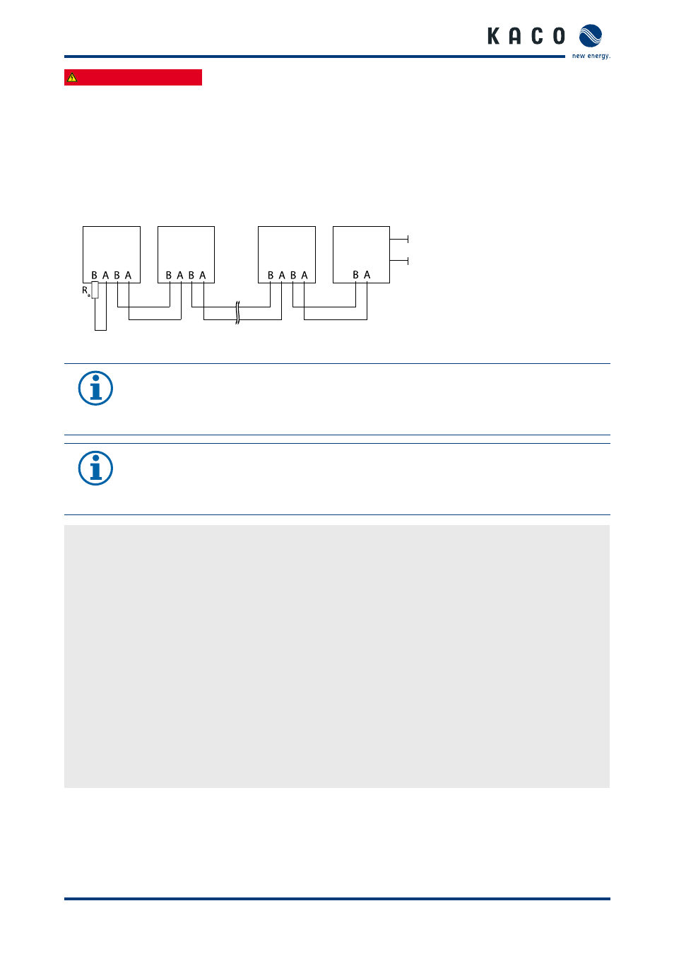
Connecting the RS485 bus
Powador
Inverter
Terminal unit
Powador
Inverter
Powador
Argus
Powador
proLOG
Communication
230 V AC
Figure 7: Example: RS485 interface wiring diagram
NOTICE
Different manufacturers do not always interpret the standard on which the RS485 protocol is based
in the same way. Note that the wire designations (- and +) for wires A and B can vary between
manufacturers.
NOTICE
Calculating efficiency by measuring the current and voltage values leads to unusable results due to
the tolerances of the measurement devices. The sole purpose of these measured values is to monitor
the basic operation of the system.
Connecting the RS485 bus
"
Maximum length of the RS485 wiring:
1,200 m under optimal conditions.
"
Maximum number of connected bus devices:
31 inverters + 1 data monitoring unit.
"
Use shielded twisted data lines.
Recommendation (using wire sleeves):
–
LI2YCYv (TP) black for laying cable outside and in the ground 2 x 2 x 0.5
–
LI2YCY (TP) grey for dry and moist indoor spaces 2 x 2 x 0.5
1. Unscrew the cable fitting (see fig. 5 on page 14).
2. Thread the connection cables through the cable fitting.
3. Connect the connection cables to the corresponding connection terminals (see fig. 8 on page 16).
4. Connect the following to all inverters and Powador-proLOG as follows:
–
Wire A (-) with wire A (-) and
–
Wire B (+) with wire B (+) (see fig. 7 on page 15)
5. Tighten the cable fitting.
6. Activate the terminating resistor on the terminal unit.