3 scaling (g50, g51), Table 3.2.3.1 scaling g codes – Yaskawa YASNAC PC NC Programming Manual User Manual
Page 72
3 - 22
YASNAC PCNC Programming Manual
Chapter 3: Movement Control Commands
external position data display unit is used, reset the present position data to “0”.
•
The tool offset amounts stored in memory are treated in a different manner between
the G20 and G21 modes.
Table 3.2.2.2
Tool Offset Amounts in G20 and G21 Modes
3.2.3
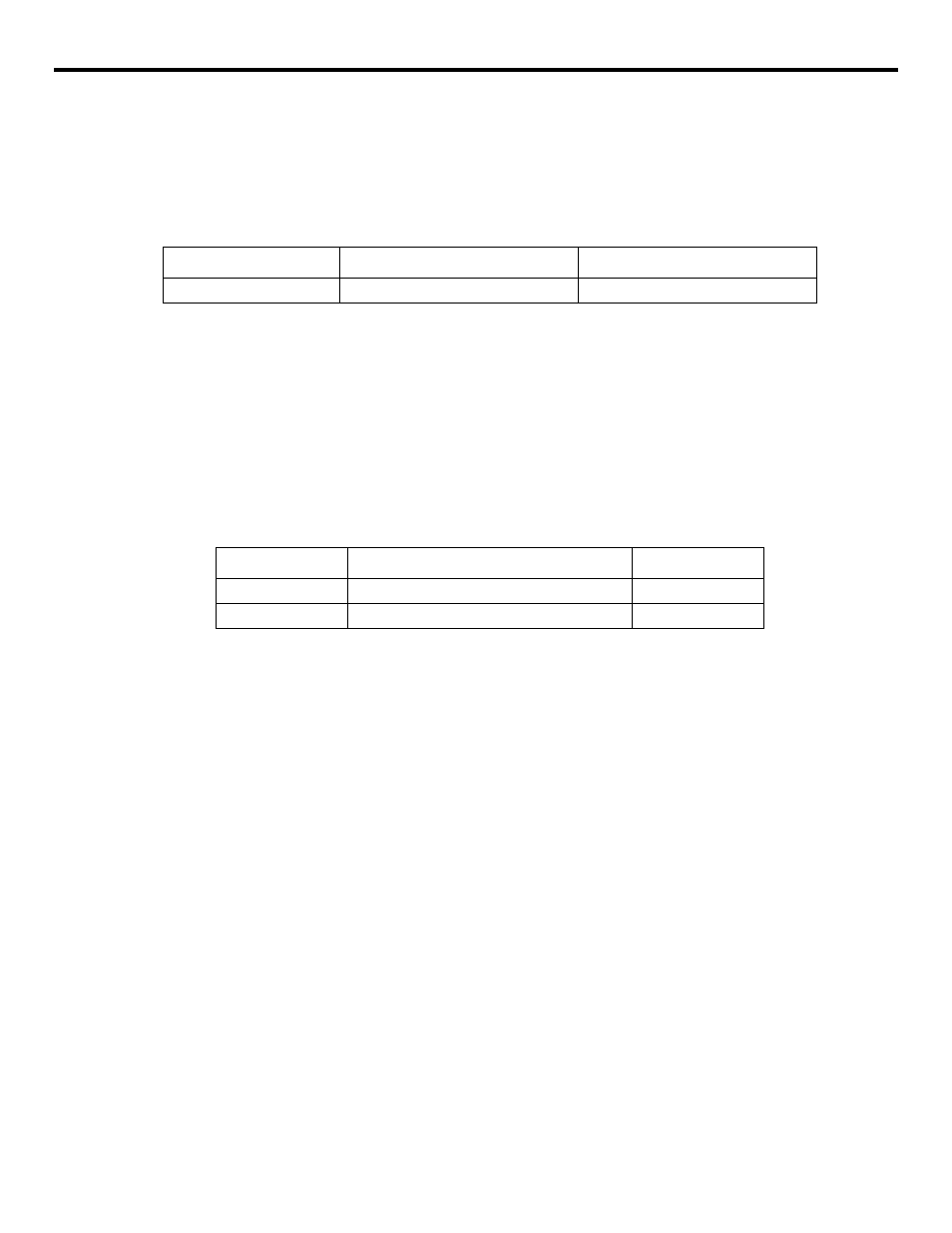
Scaling (G50, G51) *
The shape defined by a part program can be enlarged or reduced according to a required scale.
For the scaling processing, the following G codes are used.
Table 3.2.3.1
Scaling G Codes
The G50 and G51 blocks must be specified in the manner as indicated above without other com-
mands entered in these blocks. If other commands such as other G codes and X, Y, or Z are
entered in these blocks, alarm “0281” occurs.
The scaling function which is called by G51 must be canceled by G50. If G51 is specified in the
scaling mode, it is disregarded.
(1) Using the G50 and G51 Commands
•
By specifying “G511 • • • J • • • K • • • P • • •;”, a program is executed on the shape
enlarged or reduced by the ratio specified with address P. The center of scaling is
defined by I, J, and K (representing X-axis, Y-axis and Z-axis, respectively). To
establish the present position as the center of scaling, specify “G51 I0 J0 K0 P • • •;”.
•
The scaling mode can be canceled by the command of “G50;”.
•
Scaling ratio can be specified in the following range.
•
Scaling range: 0.000001 to 99.999999 times
•
Command unit of P is “1 = 0.000001”.
If a decimal point is used, the value of P is assumed to have six digits to the right of the
decimal point only in the G51 block.
Stored Offset Amount
In the G20 (Inch System) Mode
In the G21 (mm System) Mode
150000
5.9055
150.000 mm
G code
Function
Group
G50
Scaling OFF
15
G51
Scaling ON
15