Figure 2.1.3.1 rotation direction of circular arc – Yaskawa YASNAC PC NC Programming Manual User Manual
Page 35
2 - 7
YASNAC PCNC Programming Manual
Chapter 2: Commands Calling Axis Movements
•
If an optional linear 5th-axis is selected, circular interpolation is possible in the Xb,
Zb, or Yb plane which includes the 5th-axis in addition to the XY, YZ, and ZX planes.
(b = U, V, or W)
•
Circular interpolation in Xb plane
G17 G02 (or G03) X • • • b • • • R • • • (or I • • • J • • •) F • • •;
•
Circular interpolation in Zb plane
G18 G02 (or G03) Z • • • b • • • R • • • (or K • • • I • • •) F • • •;
•
Circular interpolation in Yab plane
G19 G02 (or G03) Y • • • b • • • R • • • (or J • • • K • • •) F • • •;
•
If address characters which represent the 4th- and 5th-axis are omitted as with the
commands of “G17 G02 X • • • R • • • (or I • • • J • • •) F • • •;” the XY plane is auto-
matically selected for the interpolation plane. Circular interpolation with the 4th- or
5th-axis is not possible if these additional axes are rotary axes.
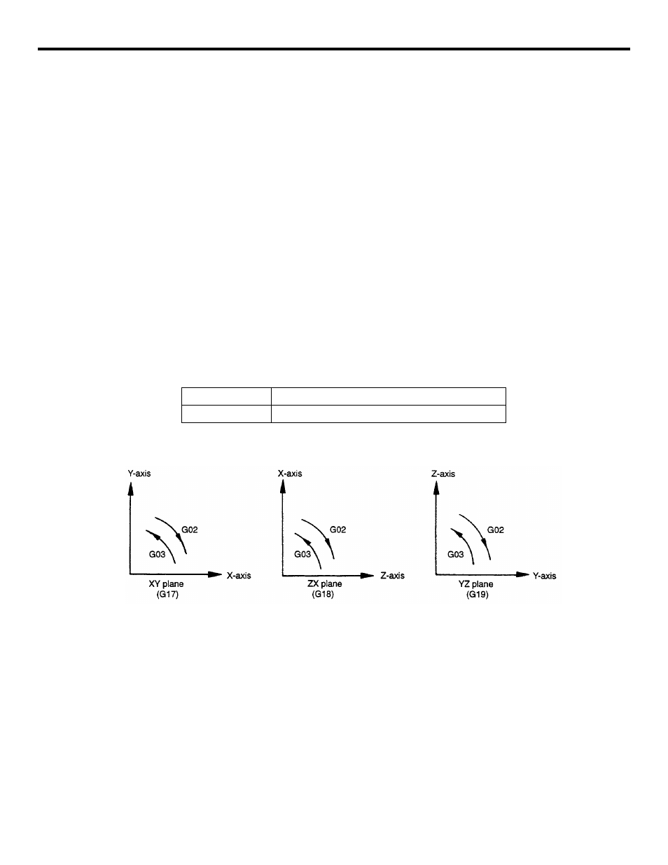
(b) Rotation direction
The direction of arc rotation should be specified in the manner indicated in Fig. 2.1.3.1.
FIGURE 2.1.3.1 Rotation Direction of Circular Arc
(c) End point
The end point can be specified in either incremental or absolute values corresponding to
the designation of G90 or G91.
G02
Clockwise direction (CW)
G03
Counterclockwise direction (CCW)