Table 4.1.7.1 programmable data input format – Yaskawa YASNAC PC NC Programming Manual User Manual
Page 203
4 - 66
YASNAC PCNC Programming Manual
Chapter 4: Enhanced Level Commands
•
Jn (n: 1 to 27) corresponds to the expanded workpiece coordinate systems.
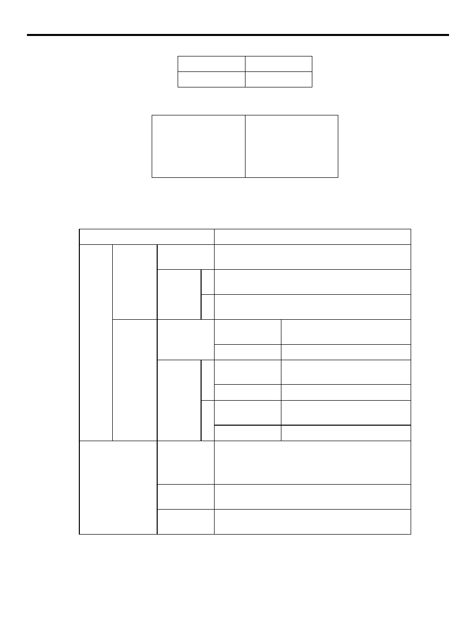
The programmable data input function is summarized in the table below.
Table 4.1.7.1
Programmable Data Input Format
Note:
When the workpiece coordinate system shift distance is changed, the specified value is saved as it
is independent
of the G90 or G91 mode.
P5
G58
P6
G59
Without J, J0 or J1
J2
•
•
•
J27
G54 J1
G54 J2
•
•
•
G54 J27
Type
Format
Offset
Tool wear
offset not
provided
H/D used in
common
G10 L10
P • • • R • • •;
G10
P • • • R • • •;
H/D used
for differ-
ent offset
functions
H
G10 L10
P • • • R • • •;
G10
P • • • R • • •;
D
G10 L12
P • • • R • • •;
G10 Q1
P • • • R • • •;
Tool wear
offset pro-
vided
H/D used in
common
Geometry offset
G10 L10
P • • • R • • •;
G10
P • • • R • • •;
Wear offset
G10 L11
P • • • R • • •;
H/D used
for differ-
ent offset
functions
H
Geometry offset
G10 L10
P • • • R • • •;
G10
P • • • R • • •;
Wear offset
G10 L11
P • • • R • • •;
D
Geometry offset
G10 L12
P • • • R • • •;
G10 Q1
P • • • R • • •;
Wear offset
G10 L13
P • • • R • • •;
Work coordinate sys-
tem shift distance
6 pairs
G10 Q2
P1 - P6 (without J, J0, J1)Axis shift
distance;
G10 L2
P1 - P6 (without J, J0, J1)Axis shift
distance;
54 pairs
G10 Q2
P1 - P6 J1 - J9Axis shift distance;
G10 L2
P1 - P6 J1 - J9Axis shift distance;
162 pairs
G10 Q2
P1 - P6 J1 - J27Axis shift distance;
G10 L2
P1 - P6 J1 - J27Axis shift distance;