Table 4.4.3.5 value of variables – Yaskawa YASNAC PC NC Programming Manual User Manual
Page 269
4 - 132
YASNAC PCNC Programming Manual
Chapter 4: Enhanced Level Commands
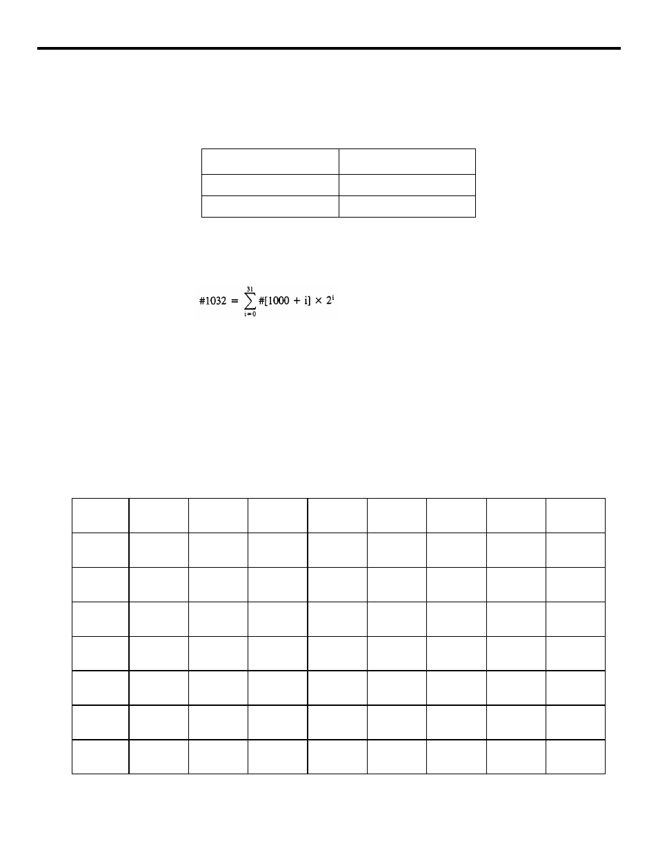
The value read to the system variables indicated above is either “1.0” or “0.0” according
to the ON/OFF state of the corresponding input signals.
Table 4.4.3.5
Value of Variables
•
By entering system variable #1032 in the right side of an operation expression, it is
possible to read the ON/OFF state of all of 32 points of input signals (U10 to U131)
collectively as a positive decimal value.
•
Note that it is not possible to enter a value by entering a system variable (#1000 to
#1032) in the right side of an operation expression.|
(b) Interface output signals
•
By entering system variables #1100 to #1131 in the right side of an operation expres-
sion, it is possible to output the ON/OFF state to each of 32-point output signal exclu-
sively used for a microprogram. The relationship between the output signals and
system variables is indicated in Table 4.4.3.6.
Table 4.4.3.6
Interface Output Signals and System Variables
Input Signal State
Variable Value
ON
1.0
OFF
0.0
System
Variables
#1107 #1106 #1105 #1104
#1103
#1102
#1101
#1100
Output
Signals
UO 7
2
7
UO 6
2
6
UO 5
2
5
UO 4
2
4
UO3
2
3
UO 2
2
2
UO 1
2
1
UO 0
2
0
System
Variables
#1115
#1114 #1113
#1112
#1111
#1110 #1109
#1108
Output
Signals
UO 15
2
15
UO 14
2
14
UO 13
2
13
UO 12
2
12
UO 11
2
11
UO 10
2
10
UO 09
2
9
UO 08
2
8
System
Variables
#1123
#1122
#1121
#1120
#1119
#1118
#1117
#1116
Output
Signals
UO 23
2
23
UO 22
2
22
UO 21
2
21
UO 20
2
20
UO 19
2
19
UO 18
2
18
UO 17
2
17
UO 16
2
16
System
Variables
#1131
#1130
#1129
#1128
#1127
#1126
#1125
#1124
Output
Signals
UO 31
2
31
UO 30
2
30
UO 29
2
29
UO 28
2
28
UO 27
2
27
UO 26
2
26
UO 25
2
25
UO 24
2
24