2 inch/metric input designation (g20, g21), Table 3.2.2.1 dimension unit selection g codes – Yaskawa YASNAC PC NC Programming Manual User Manual
Page 71
3 - 21
YASNAC PCNC Programming Manual
Chapter 3: Movement Control Commands
3.2.2
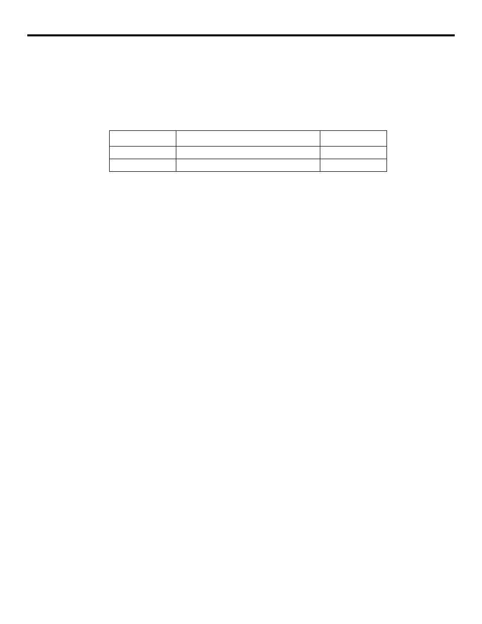
Inch/Metric Input Designation (G20, G21)
It is possible to select the dimension unit for the input data between “mm” and “inches”. For this
selection, the following G codes are used.
Table 3.2.2.1
Dimension Unit Selection G Codes
(1) Command Format
G20 and G21 should be specified at the beginning of a program in a block without other com-
mands. When the G code which selects the input dimension unit is executed, the following
values are processed in the selected dimension unit: subsequent programs, offset amount, a
part of parameters, a part of manual operation, and display.
Example of Programming
ER
CR
01234;
G20; ? Designating the input in “inch” system
•
•
•
(2) Supplements to the Dimension Unit Designation Commands
•
A parameter is used to select “inch/mm”. Therefore, the state when the power is
turned ON is determined by the setting for this parameter.
•
If the dimension unit system should be switched over during the execution of a pro-
gram, the following processing must be accomplished in advance.
•
If a workpiece coordinate system (G54 to G59) is being used, return it to the base
coordinate system.
•
Cancel all tool offsets (G41 to G48).
•
After switching over the dimension unit system between G20 and G21, the following
processing must be accomplished.
•
Execute G92 (coordinate system setting) for all axes before specifying axis move
commands.
•
If position data are displayed in a workpiece coordinate system, or when an
G code
Function
Group
G20
Input in “inch” system
06
G21
Input in “mm” system
06