7 plane selection (g17, g18, g19), Table 3.1.7.1 plane selection g codes – Yaskawa YASNAC PC NC Programming Manual User Manual
Page 68
3 - 18
YASNAC PCNC Programming Manual
Chapter 3: Movement Control Commands
3.1.7
Plane Selection (G17, G18, G19)
The plane where circular interpolation, tool radius offset, and coordinate system rotation are exe-
cuted is selected by specifying the following G code.
Table 3.1.7.1
Plane Selection G Codes
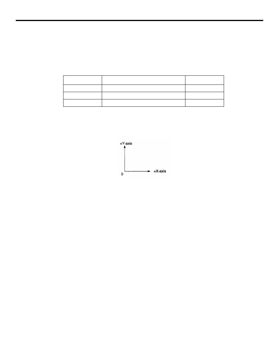
A plane is defined in the following manner (in the case of X Y plane):
The horizontal axis in the first quadrant is “+X-axis” and the vertical axis in the same quadrant
“+Y-axis”.
•
When the power is turned ON, the XY plane (G17) is selected.
•
Axis move command of a single axis can be specified independent of the selection of
plane by G 17, G18, and G 19. For example, the Z-axis can be moved by specifying “G17
Z • • •;”.
•
Execution of a canned cycle is possible only in the G17 plane (hole machining axis: Z-
axis).
•
If the 4th-axis * is selected, the following planes are added.
G17: XY plane or Xa plane
G18: ZX plane or Za plane
G19: YZ plane or Ya plane
•
If the 5th-axis * is selected, the following planes are added.
G17: XY plane or Xb plane
G18: ZX plane of Zb plane
G19: YZ plane or Yb plane
•
The plane on which the tool radius offset is executed by the G41 or G42 command is
determined by the designation of G 17, G18 or G 19; the plane that includes the rotary 4th-
or 5th-axis cannot be selected as the offset plane.
G code
Function
Group
G17
XY plane
02
G18
ZX plane
02
G19
YZ plane
02