Braking resistor installation attachment, 9 appendix 1 ratings – Yaskawa F7 to A1000 User Manual
Page 27
9 Appendix 1 Ratings
YASKAWA PL.A1000.02 F7 to A1000 - Product Transition Guide
27
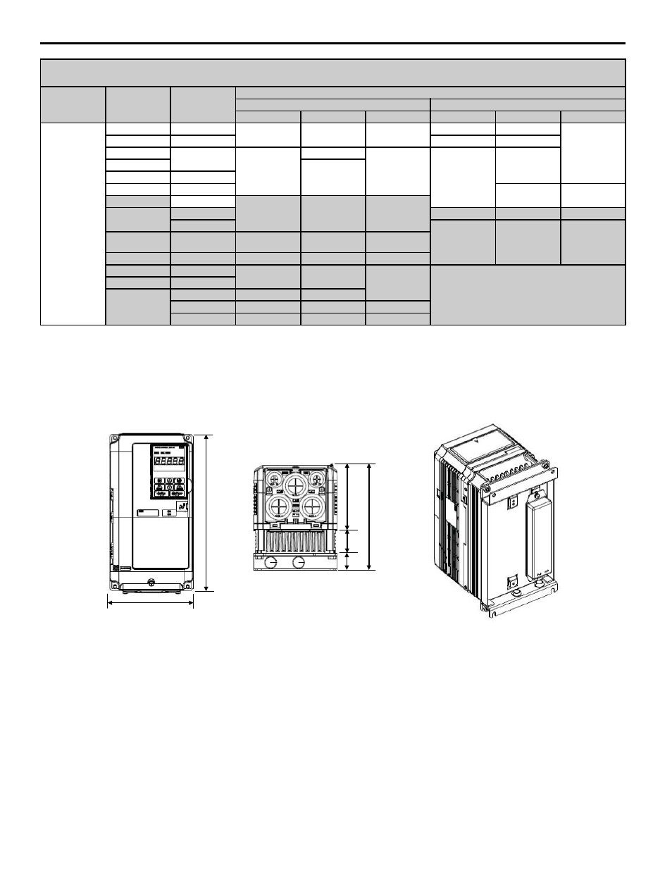
Braking Resistor Installation Attachment
The F7 allows a braking resistor to be installed directly to the unit on the backside (heatsink). The A1000 requires a
special attachment for installation. The table below lists the attachment sizes according to the drive capacity.
The attachment will increase the overall size of the drive when installing a braking resistor to certain A1000 models.
Figure 16
Figure 16 Installing a Braking Resistor on A1000 (240 V class 0.4 kW, or 0.5 HP)
(continued)
3-Phase 480 V
Class
4022
4A0058
10.98 (279)
21.06 (535)
10.24 (260)
10.00 (254)
18.31 (465)
10.16
(258)
4030
4A0072
10.98 (279)
20.28 (515)
4037
4A0088
12.95
(329)
25 (635)
11.22
(285)
12.95
(329)
24.80
(630)
4045
28.15
(715)
-
4A0103
4055
4A0139
28.74
(730)
11.14
(283)
4075
4A0165
17.72 (450)
40.44 (1027)
13.78 (350)
4090
4A0208
17.95 (456)
37.80 (960)
12.99 (330)
4A0250
19.84 (504)
45.98 (1168)
13.78 (350)
4110
4132
4A0296
19.69 (500)
48.92 (1243)
14.22 (361)
4160
4A0362
23.12 (587)
52.13 (1324)
14.96 (380)
4185
4A0414
28.43 (722)
70 (1778)
16.34 (415)
—
4220
4A0515
4300
4A0675
36.54 (928)
76 (1930)
4A0930
—
—
—
4A1200
—
—
—
NOTE:
Models noted with cell shading are provided as standard with Open/IP00 Protected Chassis. Order the appropriate NEMA Type 1/IP20 end cap kit when
NEMA 1/IP20 is required for these models.
Voltage Class
F7 Model CIMR-
F7U
A1000
Model CIMR-AU
Outer Dimensions, Inches (mm)
F7
A1000
W
H
D
W
H
D
+
:
'
'
'
'