6 main control pcb comparison – Yaskawa F7 to A1000 User Manual
Page 12
6 Main Control PCB Comparison
12
YASKAWA PL.A1000.02 F7 to A1000 - Product Transition Guide
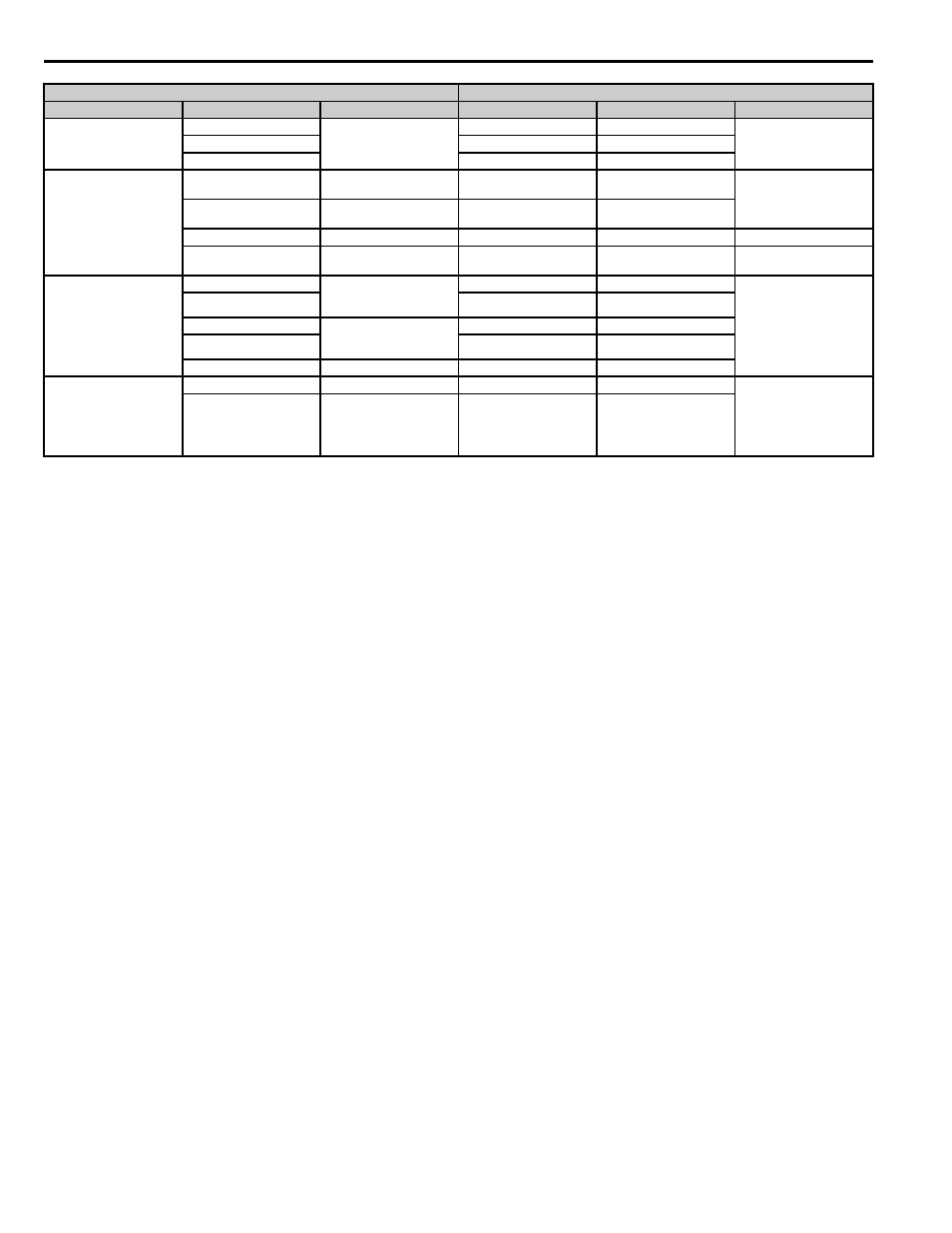
Fault Relay
MA
Fault output signal
(SPDT)
MA
N.O.
30 Vdc, 10 mA to 1 A;
250 Vac, 10 mA to 1 A
MB
MB
N.C. output
MC
MC
Fault output common
Analog Output Signals
FM
Output frequency
FM
Analog monitor output 1
(Output frequency)
-10 to +10 Vdc, or
0 to +10 Vdc
AM
Output current
AM
Analog monitor output 2
(Output current)
AC
Analog common
AC
Monitor common
0 V
MP
Pulse monitor
MP
Pulse train output (Output
frequency)
32 kHz (max)
RS-485/422
R+
Modbus communication
Differential input,
PHC isolation
R+
Communications input (+)
MEMOBUS/Modbus
communication: Use an RS-
485 or RS-422 cable to
connect the drive.
RS-485/422 MEMOBUS/
Modbus comm. protocol:
115.2 kbps (max.)
R-
R-
Communications input (-)
S+
Modbus communication
Differential output,
PHC isolation
S+
Communications output (+)
S-
S-
Communications output (-)
IG
Signal common
IG
Shield ground
Safety Monitor Output
—
—
DM+
Safety monitor output
Output status of Safe Disable
function Closed when both
Safe Disable channels are
closed.
Open Collector: +48 Vdc 50
mA maximum
—
—
DM-
Safety monitor output
common
F7 Terminal
A1000 Terminal (Designations similar to F7)
Type
F7 Terminal
Default Function
A1000 Terminal
Default Function
A1000 Description