4 terminals on the electronic assembly, Terminals on the electronic assembly – SMA SSM-U-1615 User Manual
Page 17
4.4
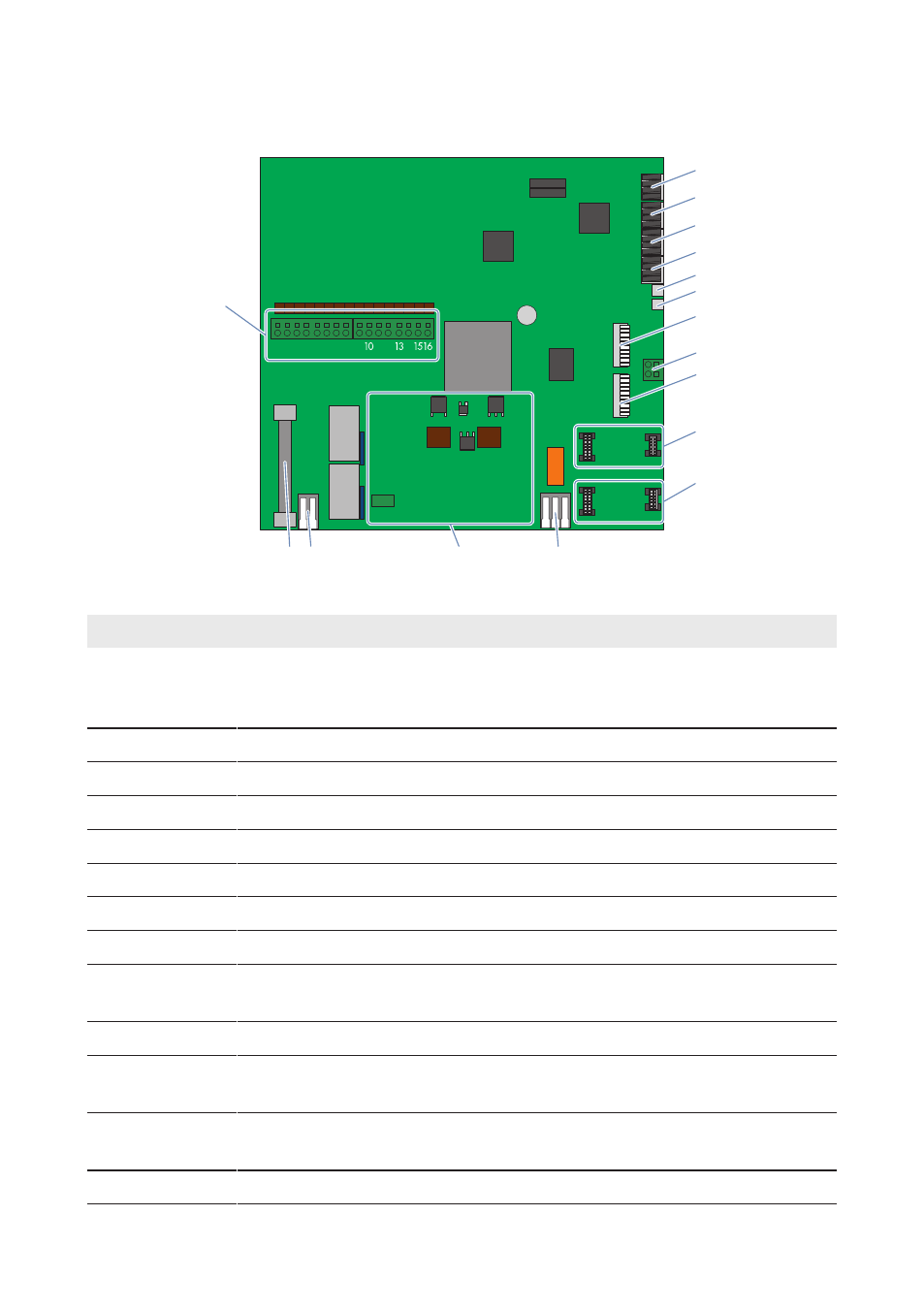
Terminals on the Electronic Assembly
1 2 3 4 5 6 7 8
9
1112
14
A
B
C
D
E
F
G
H
K
L
M
N
O
P
Q
I
Figure 6: Terminals on the electronic assembly
Position
Designation
Explanation
A
‒
Connection of string cable harnesses (PV+) and, depend-
ing on the version, of the plug-in board (MEU) for the num-
ber of PV inputs (factory installed)
B
X1
Analog current input
C
X2
Analog input temperature sensor external 1 (EXT 1)
D
X3
Analog input temperature sensor external 2 (EXT 2)
E
X4
Digital customer input
F
X5
Digital input surge arrester DC
G
X6
Status alarm contact DC load-break switch
H
X7
Ethernet communication output LAN OUT
I
X8
Terminal for the functional grounding cable of the elec-
tronic assembly
K
X9
Ethernet communication input LAN IN
L
LWLPB 1
Slot for the OF interface module (communication input
LWL IN)
M
LWLPB 2
Slot for the OF interface module (communication output
LWL OUT)
N
‒
Digital output of potential-free change-over contact
4 Product Overview
SMA Solar Technology AG
Operating Manual
17
SSMUXX15-BE-en-10