Negative grounding – SMA SB 5000-US User Manual
Page 50
Electrical Connection
SMA America, LLC
50
SB50US-80US-IA-en-37
Installation Manual
Negative Grounding
9. Tighten all cables in the terminal blocks in the DC disconnect with a torque of 15 in‑lb. (1.7 Nm).
In order to check whether your inverter is grounded as intended, observe section
6.6.2 ”DC Input Grounding” (page 48).
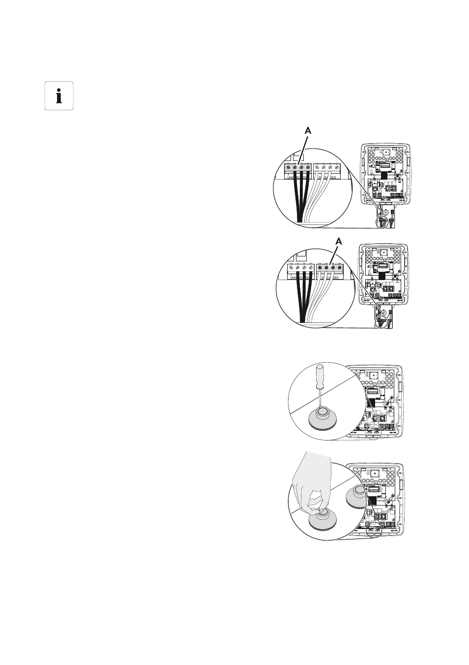
7. Connect the positive DC cables to the terminal (A)
labeled PV UNGROUNDED in the DC disconnect.
8. Connect the negative DC cables to the terminal (A)
labeled PV GROUNDED in the DC disconnect.
10. Using a screwdriver, make a hole in the left sealing
grommet.
11. Remove the rubber membrane.
2 3 5 7
A B + -
2
4
0
V
2
7
7
V
2
0
8
V
2 3 5 7
A B + -
2
4
0
V
2
7
7
V
2
0
8
V
This manual is related to the following products: