6 dc connection, Dc connection, 277 v system configuration – SMA SB 5000-US User Manual
Page 46
Electrical Connection
SMA America, LLC
46
SB50US-80US-IA-en-37
Installation Manual
10. Tighten the AC terminal blocks in the inverter with the following torques:
11. Check that all terminals have the correct wiring and that the cables are secure.
6.6 DC Connection
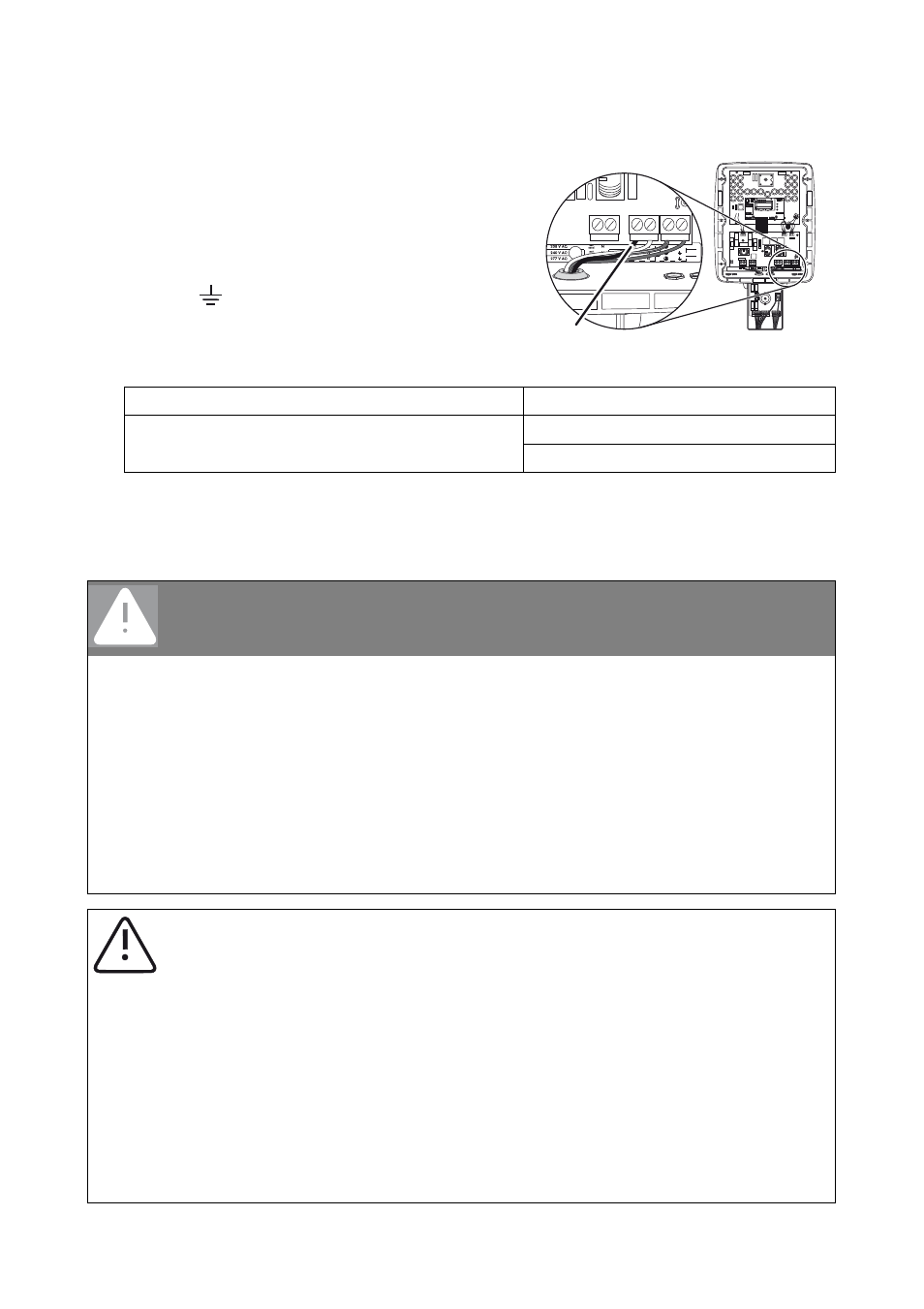
277 V System Configuration
8. Connect the white cable of the DC disconnect to the
terminal labeled N. Connect the black insulated
conductor of the DC disconnect to the terminal
labeled L1.
9. Connect the red insulated conductor to the terminal
labeled
.
Gray terminal blocks (Weidmüller)
10 … 6 AWG: 18 in-lb. (2 Nm)
Green terminal blocks (Phoenix)
8 … 6 AWG: 40 in-lb. (4.5 Nm)
10 AWG: 22 in-lb. (2.5 Nm)
DANGER
High voltages on PV modules that are exposed to light
Risk of death due to electric shock from touching a DC conductor.
• Do not touch the DC conductor.
High voltages in the DC cables
Risk of death or serious injury from touching a DC cable.
• Only connect the DC cable from the PV module to the inverter as described in this
manual.
NOTICE
Potential damage to the inverter due to overvoltage.
• The DC input voltage of the PV modules must not exceed the maximum values of the
inverter. Observe the information on the type label.
• Check the polarity and the open-circuit voltage of the PV strings before connecting
the DC cables to the inverter.
• Configure the DC input voltage range accordingly before connecting the PV modules
to the inverter. Use "Sunny Design" on www.SMA-America.com for string
configuration.
1
2
3
4
UNGROUNDED
UNGROUNDED
GROUNDED
GROUNDED
L1 L2 N
2 3 5 7
A B + -
GROUNDING
GROUNDING
ELECTRODE
ELECTRODE
CONDUCTOR
CONDUCTOR
COMBINEDCOMBINED
0
V
24
0
V
2
0
8
V
2
7
7
V
0
V
2
40
V
black