L1 n – SMA SB 5000-US User Manual
Page 45
SMA America, LLC
Electrical Connection
SB50US-80US-IA-en-37
SB50US-80US-IA-en-37
45
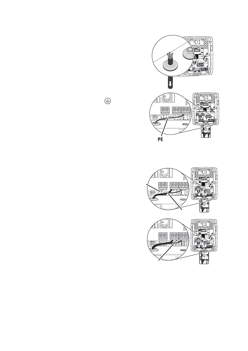
4. Pull the cable back slightly so as to seal the rubber
grommet.
5. Connect the green-yellow cable of the SMA DC
disconnect to the terminal labeled
.
208 V and 240 V System Configuration
Do not connect the Sunny Boy 8000-US to a 208 V grid.
6. Connect the white cable of the DC disconnect to the
terminal labeled N. Connect the black cable of the
DC disconnect to the terminal labeled L1.
7. Connect the red insulated conductor to the terminal
labeled L2.
2 3 5 7
A B + -
2
4
0
V
2
7
7
V
2
0
8
V
1
2
3
4
UNGROUNDED
GROUNDED
L1 L2 N
2 3 5 7
A B + -
GROUNDING
ELECTRODE
CONDUCTOR
COMBINED
2
4
0
V
2
7
7
V
2
0
8
V
L1
N
1
2
3
4
UNGROUNDED
GROUNDED
L1 L2 N
2 3 5 7
A B + -
GROUNDING
ELECTRODE
CONDUCTOR
COMBINED
2
4
0
V
2
7
7
V
2
0
8
V
L2
X
X
X