2 pr eset ting aut o matically – HEIDENHAIN TNC 320 (340 55x-03) Touch Probe Cycles User Manual
Page 76
76
3.2 Pr
eset
ting aut
o
matically
8
Measured-value transfer (0, 1)
Q303: Specify
whether the determined datum is to be saved in the
datum table or in the preset table:
-1: Do not use. Is entered by the TNC when old
programs are read in (see “Saving the calculated
datum” on page 64).
0: Write determined datum in the active datum table.
The reference system is the active workpiece
coordinate system.
1: Write determined datum in the preset table. The
reference system is the machine coordinate system
(REF system).
8
Probe in TS axis
Q381: Specify whether the TNC
should also set the datum in the touch probe axis:
0: Do not set datum in the touch probe axis
1: Set datum in the touch probe axis
8
Probe TS axis: Coord. 1. st axis
Q382 (absolute):
Coordinate of the probe point in the reference axis of
the working plane at which point the datum is to be
set in the touch probe axis. Only effective if Q381 = 1.
8
Probe TS axis: Coord. 2. nd axis
Q383 (absolute):
Coordinate of the probe point in the reference axis of
the working plane at which point the datum is to be
set in the touch probe axis. Only effective if Q381 = 1.
8
Probe TS axis: Coord. 3. rd axis
Q384 (absolute):
Coordinate of the probe point in the reference axis of
the working plane at which point the datum is to be
set in the touch probe axis. Only effective if Q381 = 1.
8
New datum for touch probe axis
Q333 (absolute):
Coordinate in the touch probe axis at which the TNC
should set the datum. Basic setting = 0
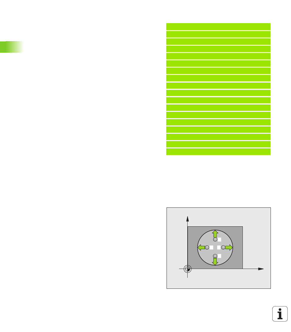
DATUM FROM INSIDE OF CIRCLE (touch probe
cycle 412, DIN/ISO: G412)
Touch probe cycle 412 finds the center of a circular pocket (or of a
hole) and defines its center as datum. If desired, the TNC can also
enter the coordinates into a datum table or the preset table.
1
The TNC positions the touch probe at rapid traverse (value from
FMAX column) following the positioning logic (see “Running touch
probe cycles” on page 21) to the starting point
1
. The TNC
calculates the probe starting points from the data in the cycle and
the safety clearance from the SET_UP column of the touch probe
table
2
Then the touch probe moves to the entered measuring height and
runs the first probing process at the probing feed rate (column F).
The TNC derives the probing direction automatically from the
programmed starting angle.
3
Then the touch probe moves in a circular arc either at measuring
height or at clearance height to the next starting point
2
and probes
the second touch point.
Example: NC blocks
5 TCH PROBE 411 DATUM OUTS. RECTAN.
Q321=+50
;CENTER 1ST AXIS
Q322=+50
;CENTER 2ND AXIS
Q323=60
;FIRST SIDE LENGTH
Q324=20
;SECOND SIDE LENGTH
Q261=-5
;MEASURING HEIGHT
Q320=0
;SET-UP CLEARANCE
Q260=+20
;CLEARANCE HEIGHT
Q301=0
;MOVE TO CLEARANCE
Q305=0
;NO. IN TABLE
Q331=+0
;DATUM
Q332=+0
;DATUM
Q303=+1
;MEAS. VALUE TRANSFER
Q381=1
;PROBE IN TS AXIS
Q382=+85
;1ST CO. FOR TS AXIS
Q383=+50
;2ND CO. FOR TS AXIS
Q384=+0
;2RD CO. FOR TS AXIS
Q333=+0
;DATUM
X
Y
1
2
4
3