2 before you start working with touch probe cycles – HEIDENHAIN TNC 320 (340 55x-03) Touch Probe Cycles User Manual
Page 19
HEIDENHAIN TNC 320
19
1
.2 Bef
o
re
Y
ou Star
t W
o
rk
ing with T
ouc
h Pr
obe Cy
cles
1.2 Before You Start Working with
Touch Probe Cycles
To make it possible to cover the widest possible range of applications
for measuring tasks, machine parameters enable you to determine the
behavior common to all touch probe cycles. If you run several touch
probes on your machine tool, these settings are globally valid for all
touch probes.
In addition, settings are available in the touch probe table that you can
separately define for each touch probe. These settings allow you to
adapt the behavior of each touch probe or a specific application (see
“Touch probe table” on page 22).
Maximum traverse to touch point: DIST in touch
probe table
If the stylus is not deflected within the path defined in DIST, the TNC
outputs an error message.
Set-up clearance to touch point: SET_UP in
touch probe table
In SET_UP you define how far from the defined (or calculated) touch
point the TNC is to pre-position the touch probe. The smaller the value
you enter, the more exactly must you define the touch point position.
In many touch probe cycles you can also define a setup clearance that
is added to SET_UP.
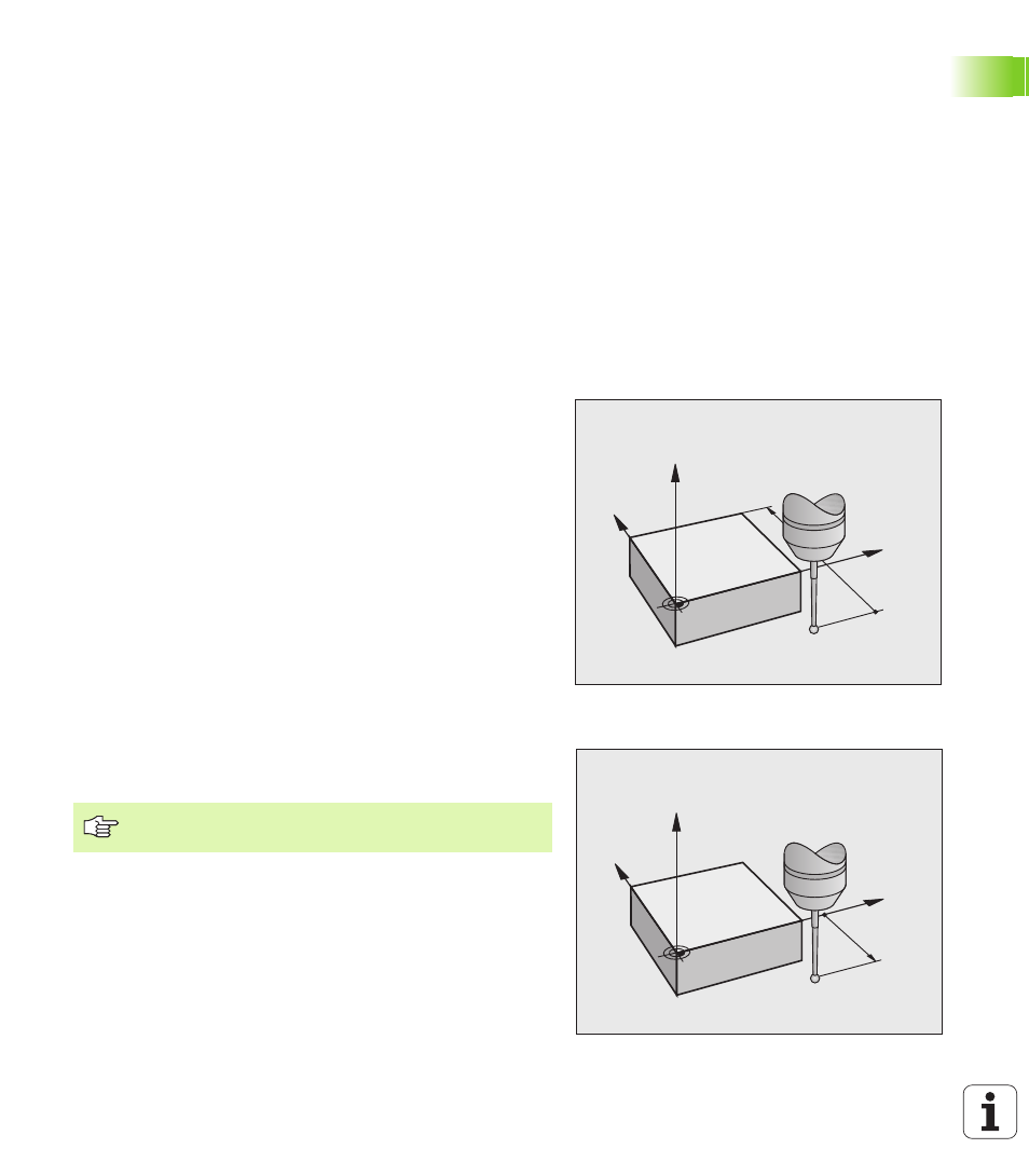
Orient the infrared touch probe to the
programmed probe direction: TRACK in touch
probe table
To increase measuring accuracy, you can use TRACK = ON to have an
infrared touch probe oriented in the programmed probe direction
before every probe process. In this way the stylus is always deflected
in the same direction.
Y
X
Z
MP6130
Y
X
Z
MP6140
If you change TRACK = ON, you must recalibrate the
touch probe.