1 measur ing w o rk piece misalignment – HEIDENHAIN TNC 320 (340 55x-03) Touch Probe Cycles User Manual
Page 54
54
3.1 Measur
ing W
o
rk
piece Misalignment
8
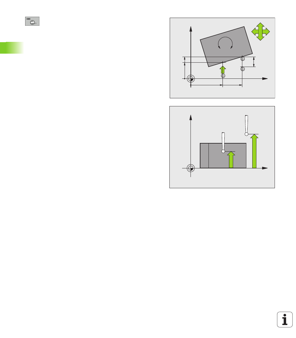
1st measuring point in 1st axis
Q263 (absolute):
coordinate of the first touch point in the reference
axis of the working plane.
8
1st measuring point in 2nd axis
Q264 (absolute):
coordinate of the first touch point in the minor axis of
the working plane.
8
2nd measuring point in 1st axis
Q265 (absolute):
coordinate of the second touch point in the reference
axis of the working plane
8
2nd measuring point in 2nd axis
Q266 (absolute):
coordinate of the second touch point in the minor axis
of the working plane
8
Measuring axis
Q272: Axis in which the
measurement is to be made:
1: Reference axis = measuring axis
2: Minor axis = measuring axis
3: Touch probe axis = measuring axis
8
Traverse direction 1
Q267: Direction in which the
probe is to approach the workpiece:
-1: Negative traverse direction
+1: Positive traverse direction
8
Measuring height in the touch probe axis
Q261
(absolute): Coordinate of the ball tip center (= touch
point) in the touch probe axis in which the
measurement is to be made.
8
Setup clearance
Q320 (incremental): Additional
distance between measuring point and ball tip. Q320
is added to column SET_UP.
8
Clearance height
Q260 (absolute): Coordinate in the
touch probe axis at which no collision between tool
and workpiece (fixtures) can occur.
X
Y
Q266
Q264
Q263
Q272=1
Q265
Q272=2
+
+
Q267
MP6140
+
Q320
A
B
C
X
Z
Q261
Q260