1 measur ing w o rk piece misalignment – HEIDENHAIN TNC 320 (340 55x-03) Touch Probe Cycles User Manual
Page 52
52
3.1 Measur
ing W
o
rk
piece Misalignment
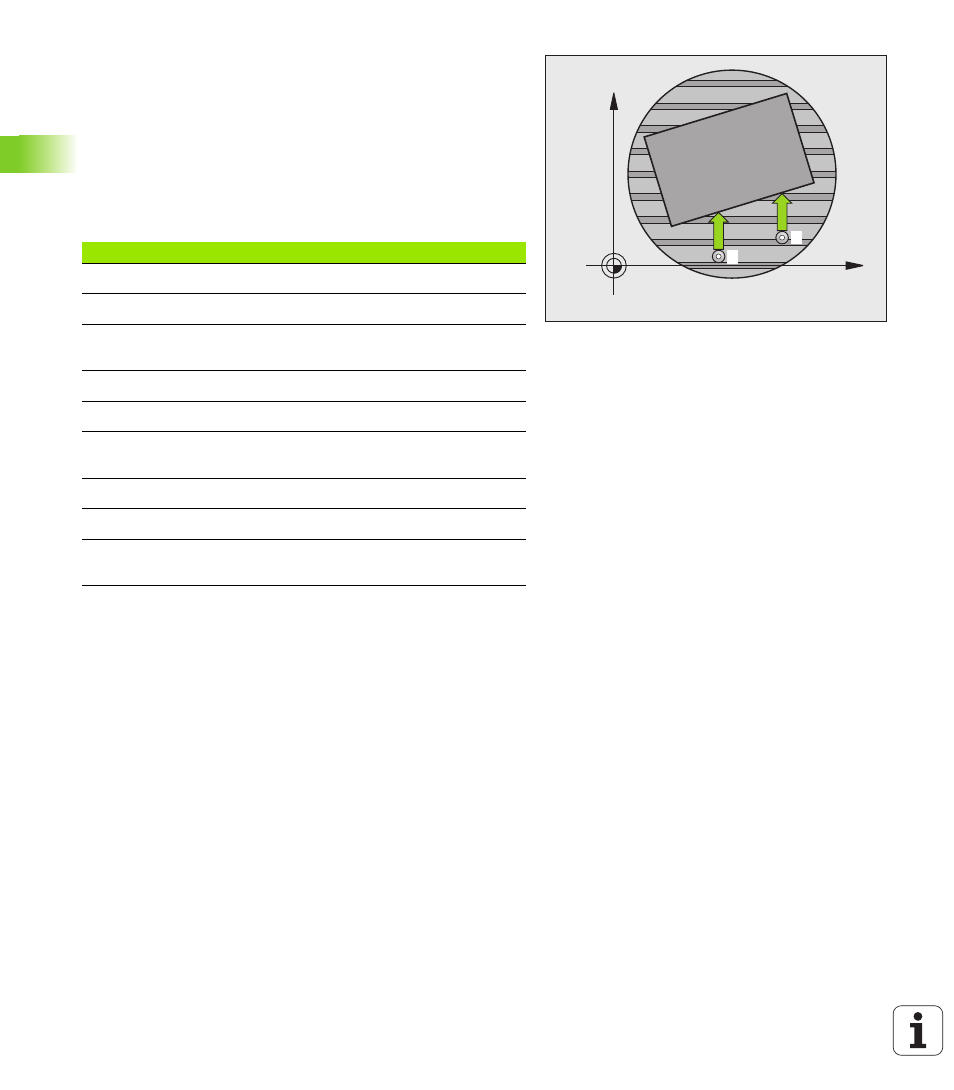
BASIC ROTATION compensation via rotary axis
(touch probe cycles 403, DIN/ISO: G403)
Touch probe cycle 403 determines a workpiece misalignment by
measuring two points, which must lie on a straight surface. The TNC
compensates the determined misalignment by rotating the A, B or C
axis. The workpiece can be clamped in any position on the rotary table.
The combinations of measuring axis (Cycle Parameter Q272) and
compensation axis (Cycle Parameter Q312) listed below are
permitted. Function for tilting the working plane:
X
Y
1
2
Active TX axis
Measuring axis
Compensation axis
Z
X (Q272=1)
C (Q312=6)
Z
Y (Q272=2)
C (Q312=6)
Z
Z (Q272=3)
B (Q312=5) or A
(Q312=4)
Y
Z (Q272=1)
B (Q312=5)
Y
X (Q272=2)
C (Q312=5)
Y
Y (Q272=3)
C (Q312=6) or A
(Q312=4)
X
Y (Q272=1)
A (Q312=4)
X
Z (Q272=2)
A (Q312=4)
X
X (Q272=3)
B (Q312=5) or C
(Q312=6)