Making power connections to the nv8140, User’s guide, Power input 1 power input 2 – Grass Valley NV8500 Series v.3.5 User Manual
Page 145
129
NV8500 Series
User’s Guide
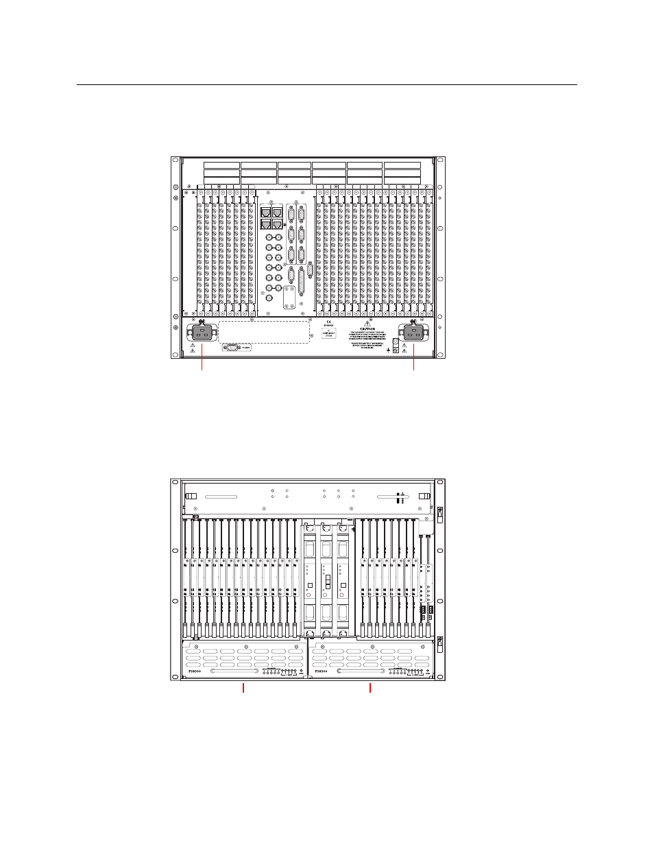
Making Power Connections to the NV8140
1 Facing the rear of the router, connect power cord WC0157 from a 20A AC power source to
Power Input 1:
Fig. 8-10: NV8140 (Rear View)
2 Repeat for Power Input 2, for the secondary supply.
3 At the front of the router, insert a PS8300 in bay 1. This is the slot for the required, primary
power supply module.
4 Install an optional redundant PS8300 power supply module in slot 2:
Fig. 8-11: NV8144 (Front View)
1
2
3
4
5
6
7
8
2
3
4
5
6
7
8
10
11
12
13
14
15
16
9
1
POWER
SUPPLY
MONITORS
TIME CODE
NVISION AUX BUS
RTR EXP OUT
RTR EXP IN
AES REF 1
AES REF 2
VIDEO REF 2
VIDEO REF 1
10/100 BT
10/100 BT
RTR EXP
RTR EXP
CTRL 1
CTRL 2
DIA
G (38.4 Kbaud)
CTRL 1
CTRL 2
DIA
G
(38.4 Kbaud)
AL
ARMS
CONTROL
PRI
PRI
SEC
SEC
100 - 240V~
15A / 7.5A
50 / 60Hz
100 - 240V~
15A / 7.5A
50 / 60Hz
Power Input 1
Power Input 2
NV8144
FAN 1
AL
ARM
PO
W
ER
FAN 2
AL
ARM
PO
W
ER
FAN 3
AL
ARM
PO
W
ER
FAN 4
AL
ARM
PO
W
ER
FAN 5
AL
ARM
PO
W
ER
Secondary
Power Supply Bay
Primary
Power Supply Bay