Making monitor signal connections, Making nv8144 monitor connections – Grass Valley NV8500 Series v.3.5 User Manual
Page 110
94
Monitoring
Making Monitor Signal Connections
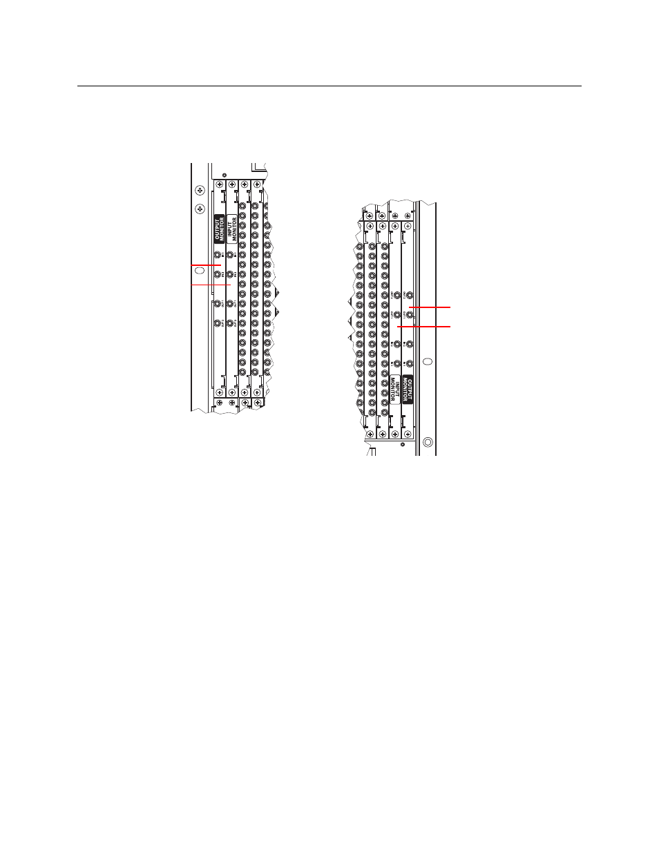
NV8576, Stand-Alone NV8576-Plus
If you are facing the rear of the router frame, the monitor backplane slots are at the left end of
the upper output bay and at the right end of the lower output bay. There are 4 slots: 2 for output
monitor backplanes and 2 for input monitor backplanes:
Fig. 5-4: Monitor Backplanes in the NV8576 and NV8576-Plus Frames
Expanded NV8576-Plus
Monitor backplanes are located, for each frame of the NV8576-Plus, as they are for the NV8576.
Making Monitor Signal Connections
If all monitor backplanes and cards have been installed, connections between the backplane
connectors and monitoring equipment can be made. Monitor connectors are coax (DIN 1.0/2.3)
and use 1855A Belden cable or equivalent.
Making NV8144 Monitor Connections
1 Face the rear of the router. The monitor backplane is at the left end of the output section.
(See Figure 1-5 on page 8.) The card has 2 connectors.
2 Connect OUTPUT MON to the section of your monitoring equipment that monitors output.
3 Connect INPUT MON to the section of your monitoring equipment that monitors input.
Output Monitor Card
Input Monitor Card
Output Monitor Card
Input Monitor Card