Grass Valley NV8500 Series v.3.5 User Manual
Page 104
88
Router Control
Making Router Control System Connections
2 To establish communication with the primary control card, connect CTRL 1 in the PRI sec-
tion, using a DE9 cable, to the router control system.
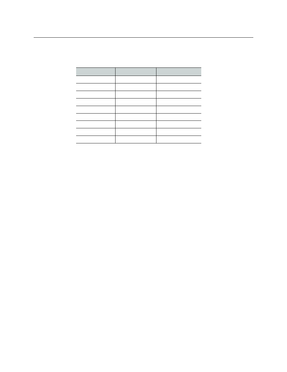
The following lists the NV9000’s pin wiring for the DE9 connectors:
Other router control systems might have different connector pinouts.
3 If a secondary control card is installed, connect to the CTRL 1 connection in the SEC section
as described in steps 2.
4 If an alternate control system (e.g., for redundancy or dual control) is being used, make con-
nections as follows:
a Connect to the CTRL 2 connection in the PRI section, using a DE9 cable to the alternate
router control system. The pinout of the CTRL 2 connector is the same as for CTRL 1.
a Connect to the CTRL 2 connection in the SEC section, using a DE9 cable to the alternate
router control system. The pinout of the CTRL 2 connector is the same as for CTRL 1.
Control End
Pins
Router End
Ground
1
Ground
Rx–
2
Tx–
Tx+
3
Rx+
Tx Common
4
Rx Common
N/C
5
N/C
Rx Common
6
Tx Common
Rx+
7
Tx+
Tx–
8
Rx–
Ground
9
Ground