Grass Valley NV8500 Series v.3.5 User Manual
Page 131
115
NV8500 Series
User’s Guide
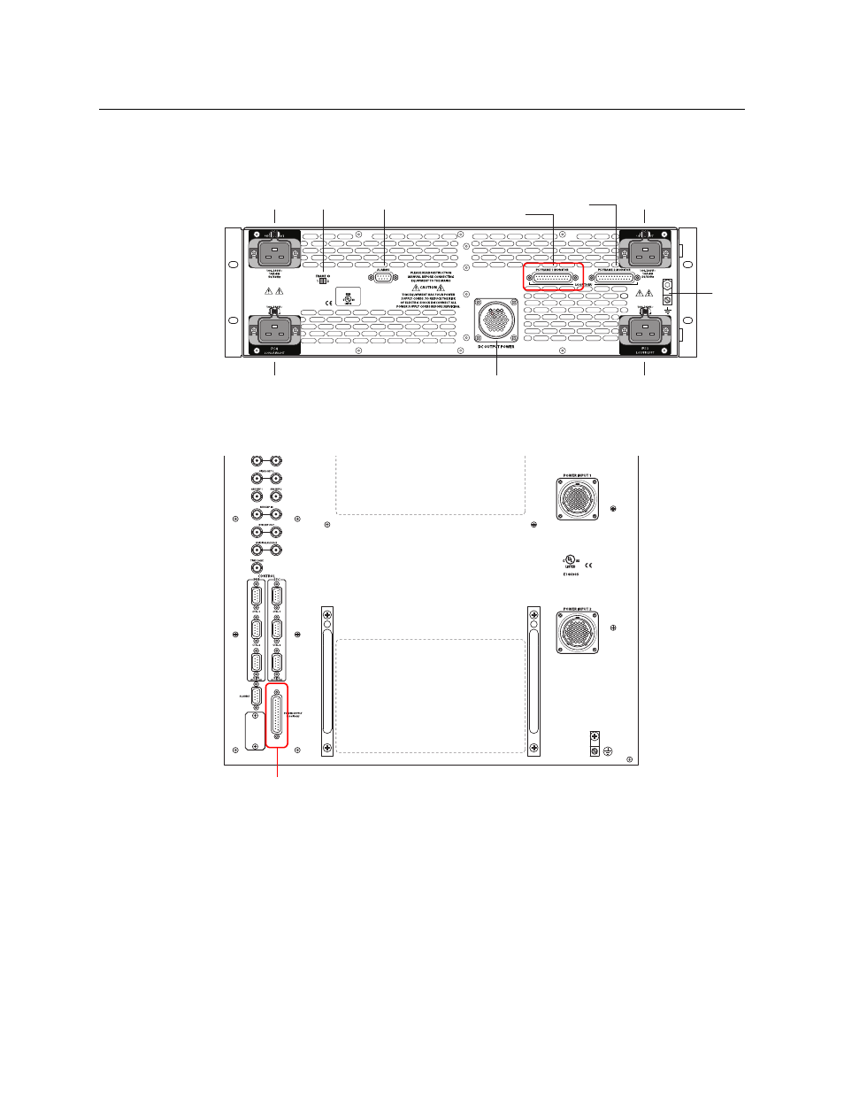
Making Power Supply Frame Connections for the NV8576 or NV8576-Plus
The NV8576 and NV8576-Plus require 2 NV8300 frames for each router frame.
1 At the rear of the one of the NV8300 frames, locate the PS Frame 1 Monitor connection.
Fig. 7-8: NV8300 Power Supply Frame (Rear View)
2 Using a WC0046-00 cable (having DB25 connectors), connect PS Frame 1 Monitor on the
NV8300 to the Power Supply Monitor connection at the rear of the router frame.)
Fig. 7-9: NV8576 power supply monitor and power connections (Rear View)
PROFESSIONAL AUDIO
AND VIDEO EQUIPMENT
PS Frame 2 Monitor
PS1
PS2
PS4
PS3
Frame ID
Alarms
DC Output
PS Frame 1 Monitor
Ground Lug
Power Supply Monitor Connector
This manual is related to the following products: