Making power connections to the nv8144, Power, Connecting to power – Grass Valley NV8500 Series v.3.5 User Manual
Page 144: Power input 1 power input 2
128
Power
Connecting to Power
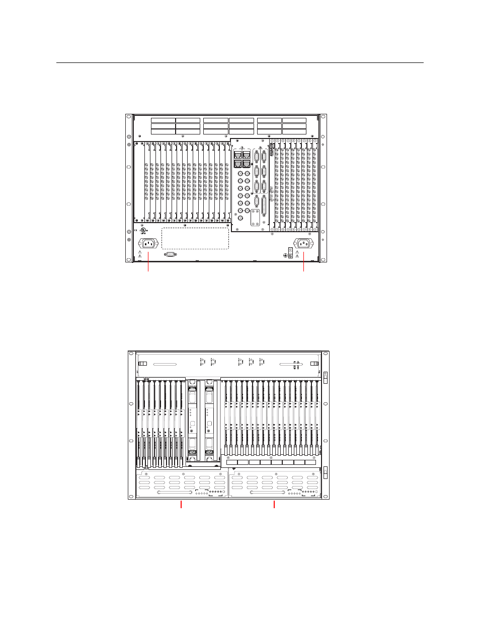
Making Power Connections to the NV8144
1 Facing the rear of the router, connect power cord WC0109 from an AC power source to
Power Input 1:
Fig. 8-8: NV8144 (Rear View)
2 Repeat for Power Input 2, for the secondary supply.
3 At the front of the router, insert a PS8100 in bay 1. This is the slot for the required, primary
power supply module.
4 Install an optional redundant power supply module in slot 2:
Fig. 8-9: NV8144 (Front View)
5 Connect the router’s ground lug to earth ground using a copper wire (14–6 AWG). The
ground lug is located in the lower right corner at the rear of the frame.
DIA
G
(38.
4 K
baud)
CONTROL
POWER
SUPPLY
i
MONITORS
TIME CODE
NVISION AUX BUS
RTR EXP OUT
RTR EXP IN
AES REF 1
AES REF 2
VIDEO REF 2
VIDEO REF 1
RTR EXP
10/100 BT
RTR EXP
10/100 BT
CTRL
1
CTRL
2
AL
ARMS
CTRL
1
CTRL
2
DIA
G
(38.
4 K
baud)
PRI
SEC
SEC
PRI
90-130V~/180-250V~
12.5A/6.25A
50/60Hz
1125 WATTS MAX
PS1
PS2
90-130V~/180-250V~
12.5A/6.25A
50/60Hz
1125 WATTS MAX
E146905
CNTRL NO. 9K50
PROFESSIONAL
VIDEO/AUDIO
ALARMS
Power Input 1
Power Input 2
NV8500
NV8500
PS8100
1 2 3 4 5
POWER
GND
1 2 3 4 5
48V
+
PS8100
1 2 3 4 5
POWER
GND
1 2 3 4 5
48V
+
Secondary
Power Supply Bay
Primary
Power Supply Bay