System alarms – Grass Valley NV8500 Series v.3.5 User Manual
Page 127
111
NV8500 Series
User’s Guide
Each of the alarm connections corresponds to a solid-state, optically isolated relay. The relay
allows current to pass in your external circuit when the alarm is on. The relay can accept up to
30 VDC and tolerate up to 75 mW. Typical applications might use the following values for circuit
1 above:
Ext. Voltage
Resistor
Current
Power
5 V
470
W
6.3 mA
19.15 mW
12 V
1600
W
6.25 mA
62.5 mW
A current of about 6 mA is sufficient to illuminate LEDs brightly.
Warning: do not reverse bias the alarm connections. They will not function and damage
might occur.
Circuit 2, in Figure 7-3, controls electromechanical relays to drive higher loads, such as lamps or
speakers, possibly using AC.
System Alarms
System alarms, so called, are router alarms.
When an alarm occurs, the connection between an alarm pin and Alarm_COM closes. When the
alarm turns off, the connection between Alarm_COM and the alarm pin opens again.
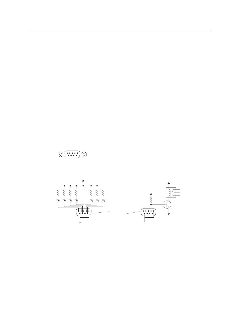
If you want a system alarm indicator, create a circuit similar to one of the circuits shown in
Figure 7-4. Each pin (2–8) monitors a specific function and activates a specific alarm.
Fig. 7-4: Alarm Connections and On/Off Switches
Each of the 7 alarm connections corresponds to a solid-state, optically isolated relay. The relay
allows current to pass in your external circuit when the alarm is on. The relay can accept up to
30 VDC and tolerate up to 75 mW. Typical applications might use the following values for circuit
1 above:
Ext. Voltage
Resistor
Current
Power
5 V
470
W
6.3 mA
19.15 mW
12 V
1600
W
6.25 mA
62.5 mW
A current of about 6 mA is sufficient to illuminate LEDs brightly.
Typical Circuit 1
Normally OFF, the LEDs turn ON to indicate failure
1
COM
75 mW max
per alarm
External Voltage Source 30 VDC max
1
2
3
4
5
6
7
8
9
1
2
3
4
5
Alarm COM
Alarm 1
Alarm 2
Alarm 3
Alarm 4
8
7
8
9
Alarm 5
Alarm 6
Alarm 7
Alarm COM
Typical Circuit 2
Customer-supplied relay (de-energized when alarm is ON)
1
COM
Ext. 5V
NC
NO
Higher Power
Loads, DC or AC
7X • • •