Making nv8576-plus monitor connections – Grass Valley NV8500 Series v.3.5 User Manual
Page 123
107
NV8500 Series
User’s Guide
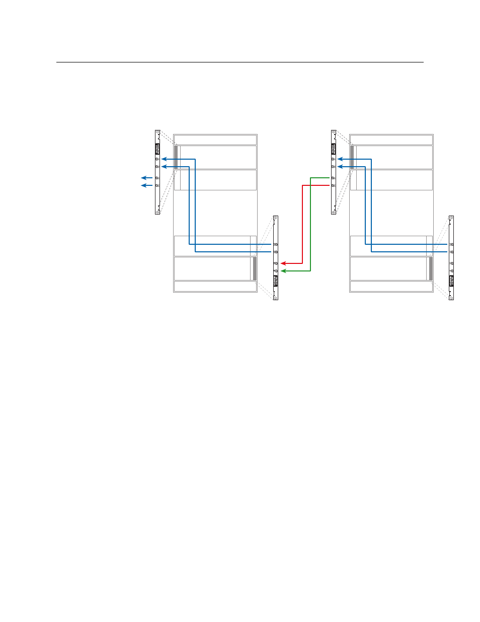
Making NV8576-Plus Monitor Connections
There are four monitor backplanes in each frame. Two are located in the upper region to the left
of the output cards as you face the rear of the frame and two are located in the lower region to
the right of the output cards.
Fig. 6-11: NV8576-Plus monitor connections (Rear View)
(Refer also Figure 1-11 on page 15.)
The monitor backplanes toward the outside of the frame are output monitor backplanes; the
backplanes toward the inside are input monitor backplanes.
For each output monitor connection, use an 1855A Belden cable (or equivalent) with coax (DIN
1.0/2.3) connectors, and make connections as shown in Figure 6-11:
1 For each frame,
Connect OUT 1 on the output monitor backplane in the lower region to IN 1 of the output
monitor backplane in the upper region.
Connect OUT 2 of the output monitor backplane in the lower region to IN 2 of the output
monitor backplane in the upper region.
2 Between the frames,
Connect OUT 1 of the upper output monitor backplane of frame 2 to IN 1 of lower output
monitor backplane of frame 1.
Connect OUT 2 of the upper output monitor backplane of frame 2 to IN 2 of lower output
monitor backplane of frame 1.
3 Connect OUT 1 and OUT 2 of the upper output monitor backplane to your monitoring
equipment.
4 Repeat steps 1–3 for input monitor cards.
Inputs
Outputs
Inputs
Outputs
Inputs
Outputs
Inputs
Outputs
To
equipment
2
Primary
Secondary
1