Signal flow and signal numbering – Grass Valley NV8500 Series v.3.5 User Manual
Page 114
98
Expanded NV8576-Plus
Signal Flow and Signal Numbering
The principal different between an NV8576 frame and an NV8576-Plus frame is that the NV8576-
Plus frame is populated with expansion output cards, while the NV8576 frame is populated with
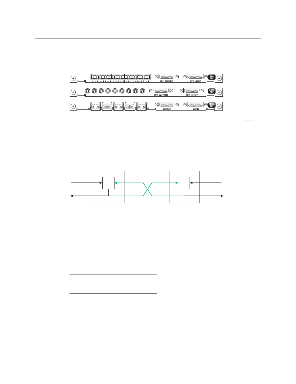
regular output cards. Expansion output cards are characterized by having 9 signal connectors
and two 28-pin “TDP” connectors for expansion cables:
For a list of expansion output cards available and their part numbers, see Appendix 16,
Signal Flow and Signal Numbering
In the expanded NV8576-Plus, each of the two frames has a 576×576 crosspoint. Expansion
cabling allows signals in one frame to reach the other frame:
Any input signal can reach any output signal in either frame. Effectively, the pair of frames is an
1152×1152 router.
The illustration above shows standard signal numbering. The structure is similar for hybrid I/O
but uses different and more complex signal numbering. (Hybrid I/O requires hybrid crosspoints
cards and hybrid control cards.)
For standard I/O, frame 1’s inputs are 1–576 and its outputs are 1–576. Frame 2’s input are 577–
1152 and its outputs are 577–1152.
For hybrid I/O, the port space for frame 1 and frame 2 are:
Hybrid I/O does not use all the ports in the space of the router (or in the spaces of the I/O cards).
I/O slots are numbered from right to left as you face the rear of the router frame. In both frames,
the slots in the upper bays are numbered 1–32. In both frames, the slots in the lower bays are
numbered 33–64.
However, I/O port numbers depend on a different slot ordering.
AES
Coax
Fiber
577-1152 Out
576 In
1576 In
576 Out
Frame 1
Frame 2
576 In
576 Out
XPT
XPT
577-1152 In
1576 Out
Frame
Video
Audio
1
1–576
1–9216
2
577–1152
9217–18432