Out 5 on, Figure 32 – H3C Technologies H3C S7500E Series Switches User Manual
Page 47
36
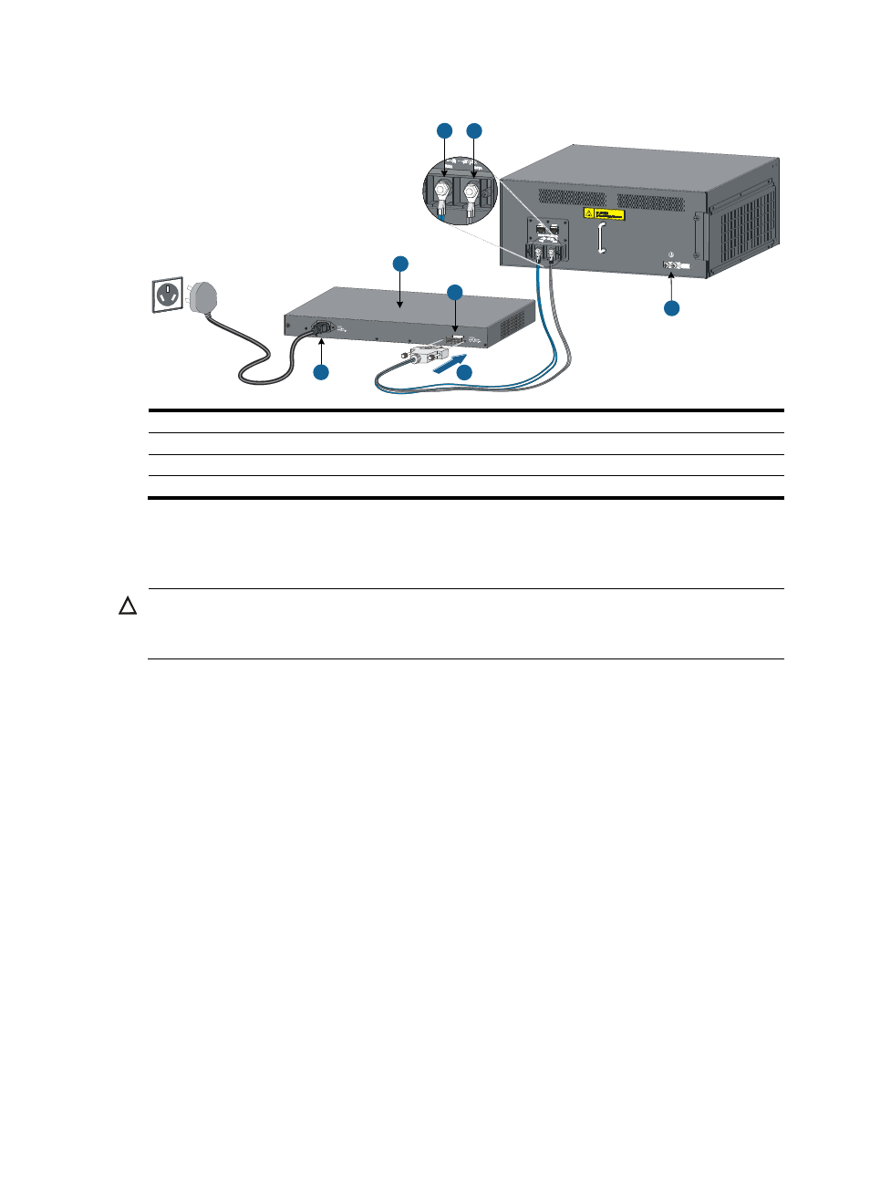
Figure 32 Connecting the RPS800-A
(1) NEG(–) terminal
(2) RTN(+) terminal
(3) Grounding point
(4) DC input
(5) Insert the H2*7 plug of the PoE power cable into the DC output
(6) AC input
(7) RPS800-A
For more information about RPS800-A, see RPS800-A User Manual.
Connecting a user-supplied power cable to the PoE input on the chassis rear panel
CAUTION:
To avoid damage to the switch, be sure to connect the negative terminals to negative terminals and
positive terminals to positive terminals.
To connect a user-supplied power cable to the PoE input on the chassis rear panel:
1.
Remove the blank panel covering the PoE port of the switch.
2.
Connect the negative OT terminal on the PoE power cable to the NEG(–) terminal on the PoE
power supply socket, and fasten the captive screw. Connect the positive OT terminal on the PoE
power cable to the RTN(+) terminal on the PoE power supply socket, and fasten the captive screw.
3.
Install the blank panel to the PoE port.
4.
Connect the PoE power cable to the external PoE power supply.
3
5
6
4
7
1
2
- H3C S12500X-AF Series Switches (3 pages)
- H3C S12500X-AF Series Switches (3 pages)
- H3C S12500X-AF Series Switches (53 pages)
- H3C S12500 Series Switches (19 pages)
- H3C MSV 50 (8 pages)
- H3C S12500 Series Switches (21 pages)
- H3C S9500E Series Switches (4 pages)
- H3C S7500E Series Switches (3 pages)
- H3C WA2200 Series WLAN Access Points (42 pages)
- H3C S12500-X Series Switches (8 pages)
- H3C SR6600 (64 pages)
- H3C S9500E Series Switches (36 pages)
- H3C WA3600 Series Access Points (237 pages)
- H3C S9500E Series Switches (270 pages)
- H3C MSR 900 (249 pages)
- H3C S12500 Series Switches (163 pages)
- H3C S12500 Series Switches (170 pages)
- H3C MSR 900 (96 pages)
- H3C MSR 900 (443 pages)
- H3C MSR 900 (468 pages)
- H3C S9500E Series Switches (32 pages)
- H3C S9500E Series Switches (241 pages)
- H3C S12500 Series Switches (39 pages)
- H3C S6800 Series Switches (59 pages)
- H3C LSBM1WCM2A0 Access Controller Module (197 pages)
- H3C S10500 Series Switches (27 pages)
- H3C LSBM1WCM2A0 Access Controller Module (226 pages)
- H3C S6300 Series Switches (188 pages)
- H3C MSR 900 (410 pages)
- H3C MSR 900 (239 pages)
- H3C WA3600 Series Access Points (394 pages)
- H3C S10500 Series Switches (2 pages)
- H3C S10500 Series Switches (2 pages)
- H3C S10500 Series Switches (2 pages)
- H3C S10500 Series Switches (2 pages)
- H3C S10500 Series Switches (2 pages)
- H3C S10500 Series Switches (2 pages)
- H3C S10500 Series Switches (2 pages)
- H3C S10500 Series Switches (1 page)
- H3C S7500E Series Switches (19 pages)
- H3C S7500E Series Switches (115 pages)
- H3C S6300 Series Switches (58 pages)
- H3C S6300 Series Switches (208 pages)
- H3C S6300 Series Switches (251 pages)
- H3C S10500 Series Switches (140 pages)