H3C Technologies H3C S7500E Series Switches User Manual
Page 30
19
2.
Remove the grounding screws from the grounding holes on the switch chassis (the grounding holes
are located at the rear of the chassis, as shown in callout 2 on
.).
3.
Use grounding screws to attach the two-hole grounding lug of the grounding cable to the chassis.
4.
Connect the other end (ring terminal) of the grounding cable to the grounding post of the
grounding strip, and fasten the grounding cable to the grounding strip with the hex nut.
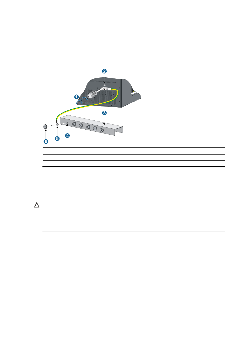
Figure 16 Connecting the grounding cable to a grounding strip
(1) Use grounding screws to attach the two-hole grounding lug to the chassis
(2) Grounding holes
(3) Grounding strip
(4) Grounding post
(5) ring terminal
(6) Hex nut
Grounding the switch through the PE wire of an AC power
supply
CAUTION:
Make sure the AC power supply uses a three-wire cable with a protection wire, and the PE wire of the AC
power supply is well grounded at the power distribution room or AC power supply transformer side. In
addition, make sure the PE connector on the switch is well connected to the PE wire of the AC power
supply.
If the switch is AC powered and no grounding strip is available at the installation site, you can ground
the switch through the PE wire of the AC power supply, as shown in