Connecting the power cable, Callout 1 on, Figure 21 – H3C Technologies H3C S7500E Series Switches User Manual
Page 35: Gent, As shown in callout 3 on, Use a phillips scr
24
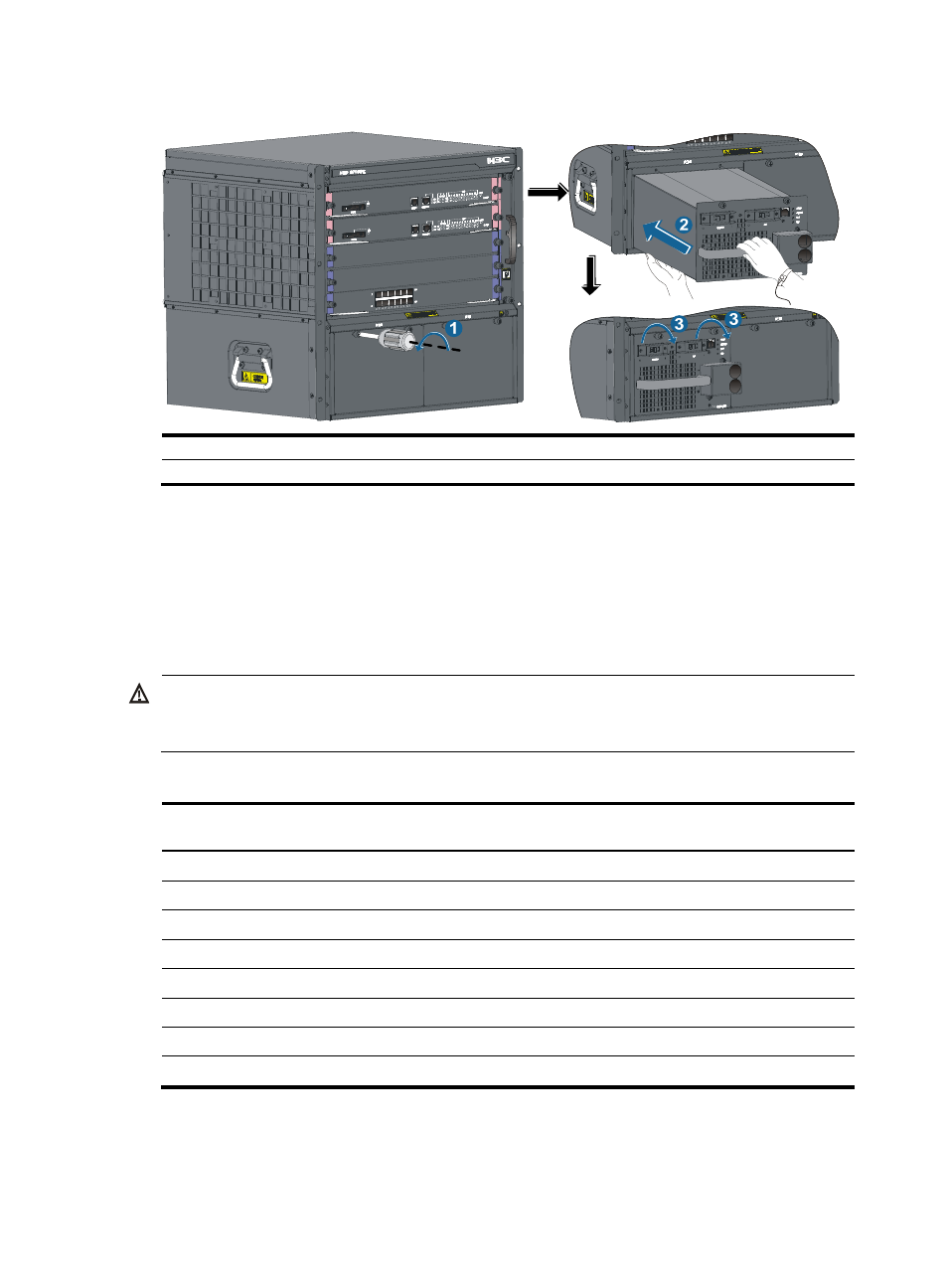
Figure 21 Installing a power module
(1) Remove the blank filler
(2) Push the power module along the guide rails into the slot
(3) Fasten the captive screws
Follow the forward inertia of the power module when inserting it into the chassis to ensure that the power
module has firm contact with the connector on the backplane.
To prevent damage to the power module and the connection terminals on the backplane, be sure to pull
out the power module first in case of any misalignment, and then push it in again.
Connecting the power cable
WARNING!
Before connecting the power cable, make sure the power module that connects to the power cable is
switched off.
Table 7 Power cable connection for the S7500E series
Model
Power input
(AC/DC)
PoE support
Description
PSR320-A AC
No
Connecting the PSR320-A/PSR650-A
PSR650-A AC
No
Connecting the PSR320-A/PSR650-A
PSR1400-A AC
No
Connecting the PSR1400-A power cable
PSR2800-ACV AC
Yes
Connecting the PSR2800-ACV power cable
PSR6000-ACV AC
Yes
Connecting the PSR6000-ACV power cable
PSR320-D DC
No
Connecting the PSR320-D/PSR650-D power cable
PSR650-D DC
No
Connecting the PSR320-D/PSR650-D power cable
PSR1400-D DC
Yes
Connecting the PSR1400-D power cable
Typically 10 A busbars are available in the equipment room but the PSR1400-A, PSR2800-ACV, and
PSR6000-ACV power modules require a 16 A power cable (AC), so you need to use a 16 A busbar, and