Configuration procedure, Fc tracert configuration example, Network requirements – H3C Technologies H3C S12500-X Series Switches User Manual
Page 117: Distributing zones
108
1.
Uplink process:
a.
Switch A adds its uplink path information (including its WWN and domain ID) to the STR
request packet and sends the packet to the next hop Switch B. After receiving the packet,
Switch B replies with an STR ACC packet to Switch A.
b.
Switch B adds its uplink path information to the received STR packet and sends it to the
destination switch, Switch C. After receiving the packet, Switch C replies with an STR ACC
packet to Switch B.
c.
Switch C adds its uplink path information to the received packet, completing the collection of
uplink path information.
2.
Downlink process:
a.
Switch C sends the STR request packet to Switch A hop by hop in the same way as in the uplink
process.
b.
After receiving the STR request packet with a downlink flag, Switch A outputs information
about all uplink and downlink switches.
Configuration procedure
Task Command
Remarks
Detect bidirectional routing
information between source
and destination.
fctracert [ -t timeout ] fcid fcid vsan vsan-id
Available in any view.
To abort the FC tracert
operation during the
execution of the command,
press Ctrl+C.
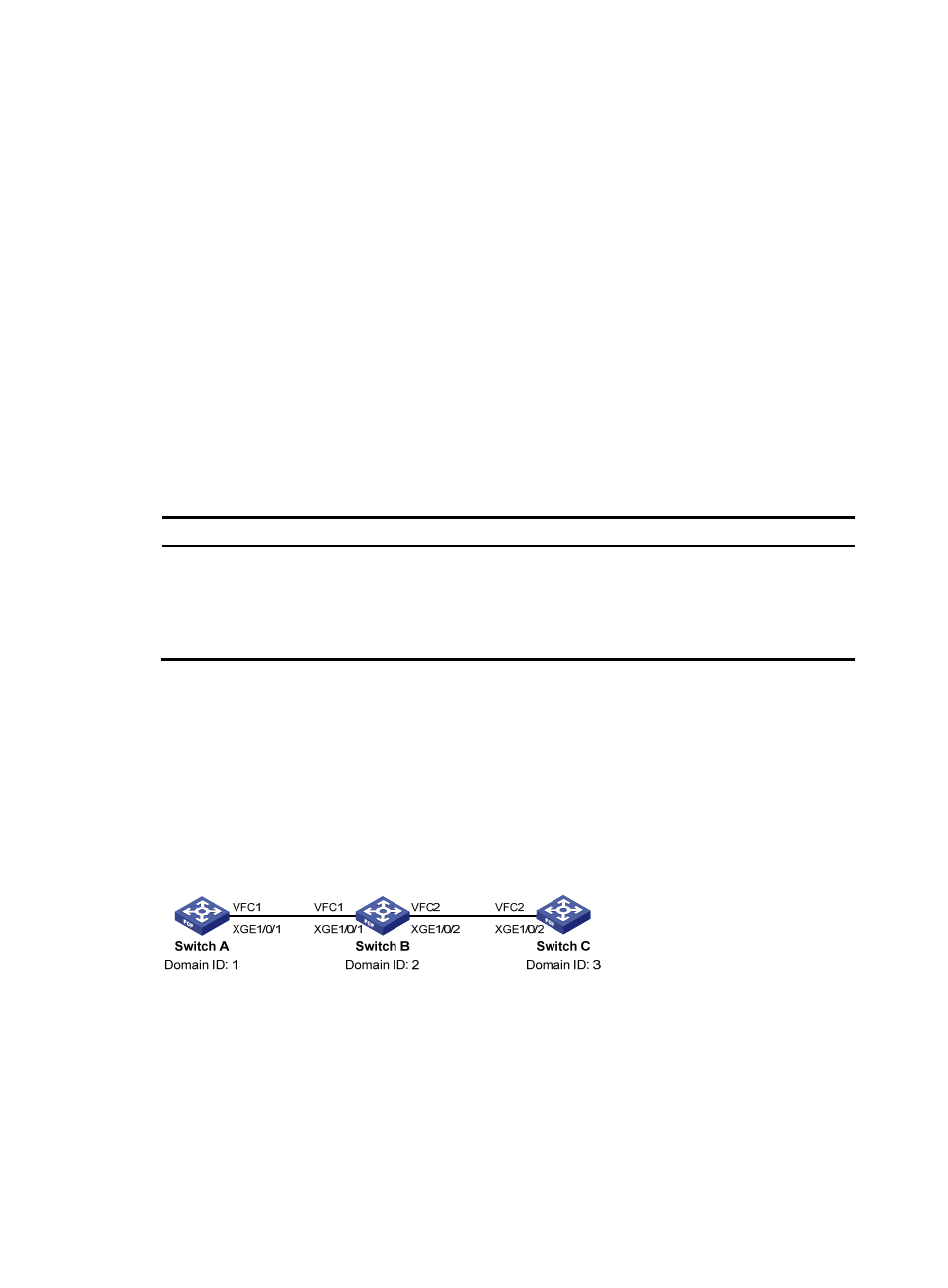
FC tracert configuration example
Network requirements
As shown in
, detect bidirectional routing information between Switch A and Switch C, and
identify the faulty node (if any).
Figure 33 Network diagram
Configuration procedure
1.
Configure Switch A:
# Configure Switch A to operate in advanced mode, save the configuration, and reboot Switch A.
(Skip this step if the switch is operating in advanced mode.)
[SwitchA] system-working-mode advance