Westermo IDW-90 AT User Manual
Page 31
31
6620-3200
The RS-232 control circuits will be described for the three different states:
no connect phase:
The TA has no ISDN connection.
The serial data (commands and responses) will be used to
configure the TA (command mode).
dial phase:
The TA has started to establish an ISDN connection and is
and
waiting for the synchronization.
disconnect phase:
The TA disconnects the existing connection
(B-channel and D-channel connection).
connect phase:
ISDN data connection is established
(D-channel and B-channel connected).
Serial data will be sent or received according to the
configured B-channel protocol (data mode).
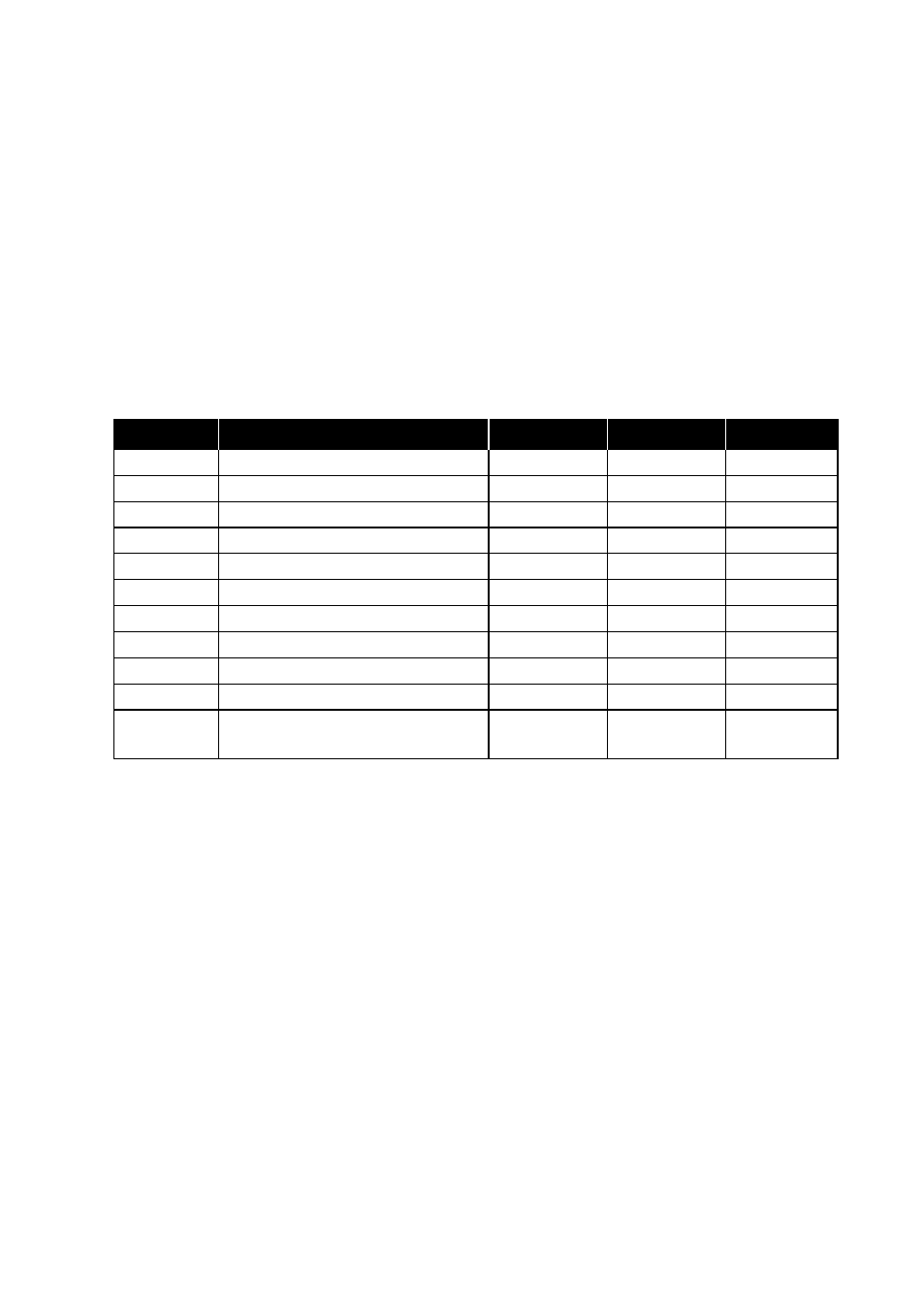
Table 3 Serial status line control
Status line Description
no connect
dial/disc.
connect
CTS
0: CTS follows RTS
=RTS/flc.*
=RTS/flc.*
=RTS/flc.**
1: CTS always ON
ON/flc.*
ON/flc.*
ON/flc.**
2: CTS follows DTR
=DTR/flc.*
=DTR/flc.*
=DTR/flc.**
DCD
0: DCD always ON
ON
ON
ON
1: DCD indicates a connection
OFF
OFF
ON
2: DCD follows DTR
=DTR
=DTR
=DTR
DSR
0: DSR always ON
ON
ON
ON
1: DSR indicates a connection
OFF
OFF
ON
2: DSR follows DTR
=DTR
=DTR
=DTR
3: DSR follows DCD
=DCD
=DCD
=DCD
5: DSR Off Hook
OFF
ON
ON
(connection establishment started)
flc.* CTS signals the serial flow control from TA (DCE) to the DTE in the command mode and
data mode (flc=5).
flc.** CTS signals the serial flow control from TA (DCE) to the DTE in the flow control modes
3 or 5 (flc=3 or flc=5).