1 led indicators – Westermo IDW-90 AT User Manual
Page 3
3
6620-3200
1.1 LED Indicators
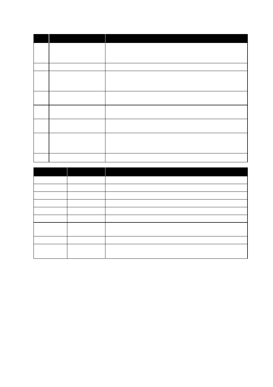
LED Function
Description
L1
ISDN Line status
LED normally showing the status of the ISDN S
0
interface.
L1 together with L2 is also used to indicate error conditions
in the IDW-90 and the connection to the ISDN S0 interface.
L2
ISDN Data connection
LED Normally showing the state of the data connection
ANL Analogue line
OFF = No analogue connection established
BLINK = Analogue call in progress
ON = Analogue line established
TD
Transmit Data
LED showing data from the DTE, the LED will blink when
data received
RD
Receive Data
LED showing data transmitted to the DTE, the LED will blink
when data transmitted
RTS
Request to Send
LED showing the status of the handshake line RTS from DTE,
LED is ON when DTE requests to send data
DCD Data Carrier Detect
LED showing the status of the handshake line DCD from
IDW-90, The behaviour of the DCD-line is programmable,
see configuration command cdcd
DTR Data Terminal Ready
LED showing the status of the handshake line DTR
L1
L2
Status
ON
5 blink/s
Start up phase
ON
OFF
S0 connection OK
ON
1 short blink/s
Call setup in progress
ON
1 long blink/s
Waiting for B channel synchronization
ON
ON
Data connection is established
OFF
OFF
No power or Hardware error
0.5 sec ON
OFF
Faulty or no S0 connection
0.5 sec OFF
OFF
2 blink/s
IDW-90 internal RAM error
OFF
0.5 sec ON
IDW-90 internal ROM error
0.5 sec OFF