Trouble shooting, Ges initiated session, Aes initiated session – Wavecom W61PC V7.5.0 User Manual
Page 286: Receiver frequency error compensation, Signal strength, Spot beam reception
276
SAT System
WAVECOM Decoder W61PC/LAN Manual V7.5
AES initiates the session.
GES Initiated Session
Through the terrestrial network, the fixed station connects to a GES. The GES sends a signaling message
to the AES on a P-channel. The MES receives signaling message and sends a response back to the GES on
a R-channel. The GES in turn sends a channel assignment signaling message for a C-channel SCPC for cir-
cuit connections and a T-channel time slot assignment for longer packet switched data connectivity to both
the MES and LES, and both stations will tune to the assigned traffic channel, where the session will take
place. After the sessions have ended channel resources are returned to the channel resource pool.
AES Initiated Session
On an R-channel the MES sends a signaling message to the GES requesting appropriate C- or T-channel
resources. The GES forwards resource allocation signaling messages on the P-channel as described above.
Some classes of AES support simultaneous data and voice traffic or more than one voice channel.
Trouble Shooting
Receiver Frequency Error Compensation
The receiver must be tuned exactly to the frequency setting received from the decoder. Any offset must
be corrected and entered into the system via the Freq Offset field in the Configuration | Receiver and
Satellite Settings... dialog.
The following procedure can be used to find out and correct this offset:
After start of the SAT Mode, wait until the receiver displays the frequency of the control channel
(see the NCSC table below and take into account down converter use)
Select spectrum analysis (VHF/UHF Modes/Analysis DIRECT/Real-time FFT) on the user in-
terface of the decoder. Make sure all the settings are still correct (Input, Offset). Select a band-
width of 24 kHz, set Averaging to about 4 or 5
The spectrum of the control channel is about 8 kHz wide, and it should be adjusted so it is in the
centre of the 24 kHz FFT display. If this is not the case, determine the frequency offset - if the
spectrum is too far to the right of the display, the sign of the offset is negative, otherwise it is pos-
itive
Now, close the FFT window, select Configurationet | Receiver and Satellite Settings....Enter
the amount and sign of the frequency offset into the Freq Offset field
Start the SAT Mode again, after the receiver has been retuned taking the frequency offset into
consideration. Select the FFT again and check if the control channel is now exactly in the middle of
the FFT display. Repeat the adjustment if necessary. It is very important that the control channel
spectrum should not be offset more than 100 Hz, i.e. it should be symmetrically centered
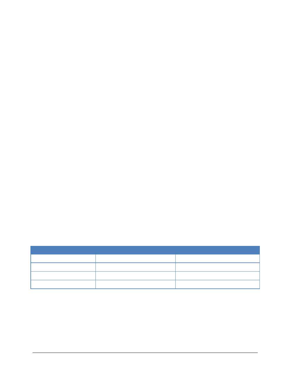
Ocean Region
NCSC Inmarsat B/M
NCSC Inmarsat miniM
AOR-W
1538.120000 MHz
1537.3100000 MHz
AOR-E
1538.220000
1537.3200000
IOR
1538.180000
1537.3400000
POR
1538.230000
1537.3300000
Signal Strength
The Signal-Noise Ratio for the control and traffic channels should be at least -18 dB as measured with the
FFT of the decoder. Depending on the location of the monitoring system, a dish size of 2 – 3 m will be
needed.
Spot Beam Reception
Traffic channels may be in spot beams allocated for power saving and frequency reuse. These spot beams
cover only a part of the ocean region for the satellite being monitored. Therefore it is possible that the
monitoring systems tunes to a frequency without signal. Nothing can be done in this case (except moving